Good China Mechanical Engineering photographs

Good China Mechanical Engineering photographs

Verify out these china mechanical engineering pictures:

Image from web page 615 of “Railway mechanical engineer” (1916)
china mechanical engineering
Image by World wide web Archive Book Pictures
Identifier: railwaymechanica95newy
Title: Railway mechanical engineer
Year: 1916 (1910s)
Authors:
Subjects: Railroad engineering Engineering Railroads Railroad vehicles
Publisher: New York, N.Y. : Simmons-Boardman Pub. Co
Contributing Library: Carnegie Library of Pittsburgh
Digitizing Sponsor: Lyrasis Members and Sloan Foundation

View Book Web page: Book Viewer
About This Book: Catalog Entry
View All Photos: All Photos From Book

Click right here to view book on-line to see this illustration in context in a browseable on the web version of this book.

Text Appearing Ahead of Image:
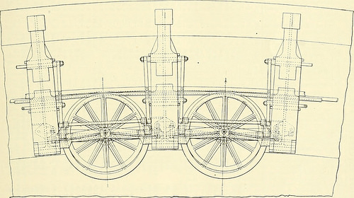
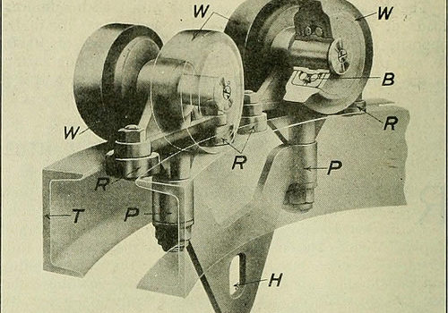
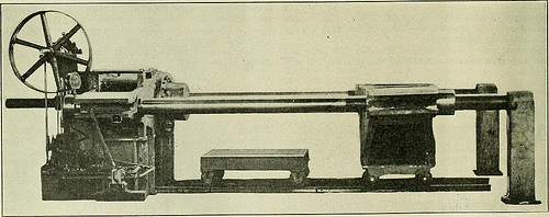
ct. The operation of this systemlightens the work and tends to make it significantly much more easy and favorablefor the workmen handling material, thereby decreasing laborturnover and increasing the efficiency of unskilled labor.The method is being manufactured and sold by the WhitingCorporation, Harvey, 111. Special Hydraulic Driving Wheel Press THE Hydraulic Press Manufacturing Company, MountGilead, Ohio, designed and constructed the unique hydraulicpress, illustrated, which was not too long ago sold by the Mc-Carter Cooper Company, New York, to the Compagnie Gen-eral De Chemins De Fer &amp Tramways en Chine, Pekin,China. This press is utilized for forcing driving wheels on or off between strain bars is 84 in. and in between ram and resistancehead is 108 in. maximum. This may be decreased to 78 in.by moving the resistance head, which is mounted on wheels.The press is also equipped with a belt-driven energy attach-ment and three plunger pump with each low and high pres-positive plungers. The pump is equipped with hand and pres-

Text Appearing Soon after Image:
Hydraulic Press for Applying Driving Wheels to Crank Axles the crank-axles of locomotives, a special style of press beingnecessary due to the fact of the crank throws. The press will manage wheels 80 in. in diameter and significantly less,becoming capable of exerting a force of 330 tons. The distance certain knock-outs whereby any one particular or all pump cylinders perhaps eliminated from service at will or automatically when themaximum pressure is reached. A little hydraulic cylinderand ram returns the main ram to its beginning position. Railway

Note About Photos
Please note that these pictures are extracted from scanned page photos that may have been digitally enhanced for readability – coloration and appearance of these illustrations may not perfectly resemble the original perform.

Cool Mechanical Engineering China images

Cool Mechanical Engineering China images

Some cool mechanical engineering china photos:

Image from web page 421 of “Morton memorial a history of the Stevens institute of technologies, with biographies of the trustees, faculty, and alumni, and a record of the achievements of the Stevens family of engineers” (1905)
mechanical engineering china
Image by Web Archive Book Images
Identifier: mortonmemorialhi00furm
Title: Morton memorial a history of the Stevens institute of technologies, with biographies of the trustees, faculty, and alumni, and a record of the achievements of the Stevens household of engineers
Year: 1905 (1900s)
Authors: Furman, Franklin De Ronde, 1870- ed
Subjects: Stevens family members Morton, Henry, 1836-1902 Stevens Institute of Technologies
Publisher: Hoboken, N.J., Stevens institute of technology
Contributing Library: The Library of Congress
Digitizing Sponsor: The Library of Congress

View Book Page: Book Viewer
About This Book: Catalog Entry
View All Pictures: All Images From Book

Click right here to view book on-line to see this illustration in context in a browseable online version of this book.

Text Appearing Ahead of Image:
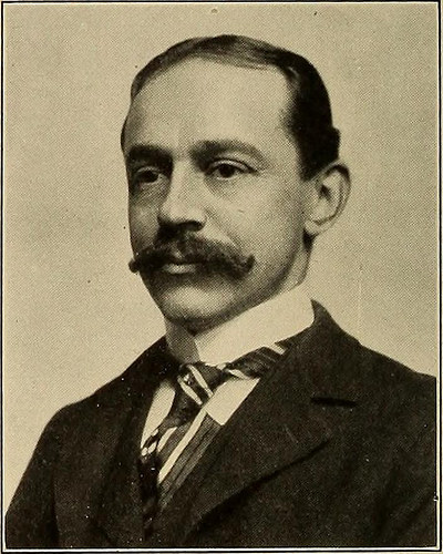
1899.He has two youngsters, William Arnaud andMadeleine Arnaud Fox. Fraentzel, Frederick C. (M.E., 83), wasborn in Newark, N. J., June 4, 1862. He wasassistant in the department of maintenanceof ways of the Pennsylvania Railroad, JerseyCity, 1883 in the shops of the Pittsburg,Chicago, &amp St. Louis Railroad, Logansport.Ind., 1883-84 and first assistant engineerwith the Celluloid Manufacturing Co., New-ark, N. J., 1884-85. He has been a memberof the firm of Campbell &amp Co., Newark, N. J.,mechanical engineers, solicitors of patents,and specialists in patent causes, from 1885 todate. Given that the death of Mr. Campbell in1887 Mr. Fraentzel has continued the busi-ness alone at the exact same place. Fie has a largenumber of prominent customers, and he hasacted as patent agent for James E. Sague,A. H. Hickok, and E. D. Estrada, all of theClass of 83, in securing United States andforeign patents for them. He is also secre-tary and treasurer of the Electra Manufac-turing Co., Newark, and a member of the

Text Appearing Right after Image:
F. C. Fraentzel Board of Trade, the Newark Club, the Re-publican Club of Newark, N. J., and of theFreylinghuysen Lancers. Mr. Fraentzel is the son of H. Hugo R. THE ALUMNI 393 and Regina Fraentzel. He married LillieBlewett (deceased), February five, 1885 andWillmia Blewett, September 30, 1890. Hehas one particular child, Frederick H. W. Fraentzel. Frank, Emil H., Jr. (M.E., 98), was withthe Edison Electric Illuminating Co., NewYork, 1898-99 and with the American Pa-per Goods Co., Kensington, Conn., 1899-1900. He has been constructing engineerand draughtsn-fan for the Electric LaunchCo., Bayonne City, N. J., from 1900 to date. Frazar, Everett Welles (M.E., 90), wasborn in Shanghai, China, August 17, 1867.He was laboratory assistant with ThomasShaw, Philadelphia, 1890-91 engaged in ex-perimental function in the laboratory of ThomasA. Edison, Orange, N. J., 1891 and was as-sistant manager of the Sims-Edison Elec-trical Torpedo Co., 1891-93. In March, 1892, he went to France, wherehe constructed and te

Note About Photos
Please note that these pictures are extracted from scanned page images that might have been digitally enhanced for readability – coloration and look of these illustrations may possibly not perfectly resemble the original function.

Image from page 416 of “American engineer and railroad journal” (1893)
mechanical engineering china
Image by World wide web Archive Book Images
Identifier: americanengineer67newy
Title: American engineer and railroad journal
Year: 1893 (1890s)
Authors:
Subjects: Railroad engineering Engineering Railroads Railroad vehicles
Publisher: New York : M.N. Forney
Contributing Library: Carnegie Library of Pittsburgh
Digitizing Sponsor: Lyrasis Members and Sloan Foundation

View Book Page: Book Viewer
About This Book: Catalog Entry
View All Pictures: All Images From Book

Click right here to view book online to see this illustration in context in a browseable on the internet version of this book.

Text Appearing Just before Image:
(launches)a .quick distance upriver, and I understand they are doing a■very profitable organization. INFLUENCE OF TEMPERATURE ON THEMECHANICAL PROPERTIES OF BRASS ONANNEALING. We know that the mechanical properties of hammered brassare very significantly modified by annealing. An examinationof the variation of these properties, due to the action of an-nealing temperatures, has been created with the view of detcr-

Text Appearing Following Image:
Program OF CURVE PULLEYS FOE CABLE RAILWAY. If it is possible for companies to develop an engine thatcan be placed in the boats utilized right here, I think that there wouldsoon be a huge demand for such engines. The canals are theonly roads, and all travel is, of course, by boat. The trafficcarried on by boats is very big. The introduction of quickermethods of travel would be hugely appreciated, particularly Ifthe Taotai sets the example, and I deem this a most auspicioustime to introduce our strategies into this province. Some years ago I saw in Washington a boat which I thinkwould be specially nicely adapted for China. If I rec iUectaright, it was a petroleum launch produced in Providence. R. I.,by Brayton but such rapid strides have been made since thentliat i)0ssibly there might be more appropriate sorts on the marketnow. For the guidance of interested parties the following de-scription may be of some use : Length, 33 ft. breadth, 6 ft.ten in. height, from keel to rail, two ft. height, from rail to t

Note About Pictures
Please note that these photos are extracted from scanned page images that could have been digitally enhanced for readability – coloration and look of these illustrations may not completely resemble the original function.

Differentiating Electrical Engineering and Mechanical Engineering

Differentiating Electrical Engineering and Mechanical Engineering

Electrical engineering a study of the sensible makes use of of power systems. Electrical Engineers will frequently specialise in 1 or two diverse places of power for example: Gas, hydro energy, fuel cells, solar power, geothermal energy or wind energy. Mechanical engineering is also focused on the practical side of factors but in this case focusing on designing, developing and installing machinery, tools, devices and elements. It is the broadest and oldest engineering profession and the engineer can draw knowledge from a range of technical locations for example: thermodynamics, kinetics, fluid mechanics and elements of electronics.

Each electrical engineers and mechanical engineers perform on a contract as a consultant to organisations or full-time on a ‘project-to-project’ basis so they tend to suit ambitious folks who like to be challenged and operate nicely in groups. Mechanical contractors will frequently specialise in an business such as industrial gear for plants, aeronautics, automotive, customer electronics or robotics.  Electrical contractors can specialise in the following sectors:  Telecommunications, Energy and Electric Power, Computer systems, Semiconductors, Aerospace, Bioengineering, Manufacturing, Solutions and Other Professions and Education/Investigation

As you might have gathered from the above data, both electrical engineering and mechanical engineering are broad fields of study and fairly frequently you will require to seek out a specialist with specific education and knowledge in work connected to your project.

Electrical and Mechanical Contractors typically meet on projects involving industrial and industrial buildings ranging from new builds to current facility upgrades. For example several manufacturing plant setups will call for each specialists in each machinery and energy systems. In this case an electrical contractor would install the power systems, connected circuitry/cabling as well as guaranteeing that any information centres are adequately powered.  The function, size and place of a building will influence its energy requirement and fairly typically an electrical engineer will need to have to intelligently integrate the electronics of larger commercial buildings with its communications and details technologies infrastructure to make sure smooth operation. The mechanical engineer would oversee all elements of instrumentation and procedure handle machinery such as any component specialisation for distinct manufacturing tactics.

No matter whether dealing with buildings or customer items the emphasis of either field is, usually speaking, driving more and a lot more towards combining energy efficiency with decreasing the size of units/components and machines. A talent in innovation as properly as wonderful networking capabilities would be excellent qualities in both electrical contractors and mechanical contractors since neither profession operates in isolation.

The King Moffatt group staff some of the ideal electrical contractors and mechanical contractors in the UK and Ireland for a range of industrial and industrial projects. http://www.kingmoffatt.com

Good Mechanical Engineering China pictures

Good Mechanical Engineering China pictures

Some cool mechanical engineering china pictures:

Image from web page 182 of “An American engineer in China” (1900)
mechanical engineering china
Image by World wide web Archive Book Images
Identifier: cu31924023226081
Title: An American engineer in China
Year: 1900 (1900s)
Authors: Parsons, William Barclay, 1859-1932
Subjects: Parsons, William Barclay, 1859-1932 Railroads
Publisher: New York, McClure, Phillips &amp co.
Contributing Library: Cornell University Library
Digitizing Sponsor: MSN

View Book Web page: Book Viewer
About This Book: Catalog Entry
View All Pictures: All Images From Book

Click here to view book on the web to see this illustration in context in a browseable on the internet version of this book.

Text Appearing Before Image:
ame on the base, they would beconsidered of Chinese make. They are inex-pensive, of the sort preferred by the Chinaman,although perhaps not for sale in Hamburg orBerlin. On the other hand, the American article,considerably more handsome, from our point of view,but also a lot more high-priced, is of the exact same style as issold on Broadway in New York. There is no want to multiply examples. Thereawaits the American manufacturer an outlet, espe-cially for tools, machinery, and other articles iniron and steel. He will find a demand for thesmaller and lighter machines, rather than for thelarger ones. That is to say, he must appeal firstto the person worker who exists now, ratherthan aim at the needs of a conglomeration in afactory which will come about in the future. The Chapter V: Industrial Relations 177 totals should be basic in character, casil WMirketlami kept in ortler, ami without tlie applicationof fast-return and other mechanical devices s&lttnecessary lor labor-saviiicr with us. Litiht W(jod-

Text Appearing Soon after Image:
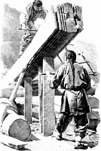
A Chinese Saw-mill The teeth of the saw are arranged to reduce on the up stroke alternatively oton the down, as in other countries operating machiner} can be made to supplant thepresent manual-labnr techniques and a laroe fieldis open for all sorts oi pumps, windmills, piping-,and other articles of Inrlraulic machinerv. Cott(jn g(jods of the finer grades, as properly as the 178 An American Engineer in China coarser which are supplied, household articles ofall kinds, glassware, window-glass, wall-paper,and plumbing fixtures will find a prepared market,as will also farm equipments, such as light-wheeledvehicles and small agricultural implements of allkinds. In these, as in a lot of manufactured arti-cles, American trade has as yet made little or noimpression and yet the American post has anacknowledged superiority over any other for-eign make. It is essential for us also to study the China-man himself. The English and American tradersmake but small try to find out the language, andtherefore frequently f

Note About Pictures
Please note that these images are extracted from scanned web page images that might have been digitally enhanced for readability – coloration and appearance of these illustrations may possibly not perfectly resemble the original function.

Image from web page 124 of “American engineer and railroad journal” (1893)
mechanical engineering china
Image by Internet Archive Book Images
Identifier: americanengineer77newy
Title: American engineer and railroad journal
Year: 1893 (1890s)
Authors:
Subjects: Railroad engineering Engineering Railroads Railroad automobiles
Publisher: New York : M.N. Forney
Contributing Library: Carnegie Library of Pittsburgh
Digitizing Sponsor: Lyrasis Members and Sloan Foundation

View Book Page: Book Viewer
About This Book: Catalog Entry
View All Images: All Photos From Book

Click right here to view book on-line to see this illustration in context in a browseable online version of this book.

Text Appearing Before Image:
co, the firststop to be at Honolulu. From there he goes to Japan, Koreaand Slam, and from China he will travel more than the Trans-Siberian Railroad to Russia. He plans to go to every countryin Europe. Mr. Gross will be absent from this nation abouta year. The goal of his trip is to make a careful investi-gation of the opportunities for American locomotives in theOrient and European nations and to establish systematicbusiness relations. Mr. Gross will be accompanied on his tripby Cliarles M. Muchnic, till recently mechanical engineer ofthe Denver &amp Rio Grande, who will act as Mr. Gross secretary. Mr. Max Toltz has resigned as mechanical engineer of theGreat Northern Railway. He is engaged in superintendingthe application of his system of acetylene car lighting to alarge quantity of vehicles on the Canadian Pacific, and has beenretained by that road in a consulting engineering capacity inconnection with the new shops at Montreal. March, 1903. AMERICAN ENGINEER AND RAILROAD JOURNAL. Ill

Text Appearing After Image:
nniDD DD

Note About Pictures
Please note that these images are extracted from scanned page images that may have been digitally enhanced for readability – coloration and look of these illustrations could not completely resemble the original operate.

110824-N-XR557-038
mechanical engineering china
Image by Cooperation Afloat Readiness and Coaching (CARAT)
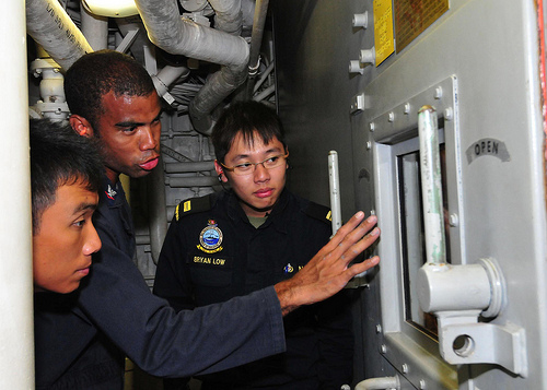
110824-N-XR557-038 SOUTH CHINA SEA (Aug. 24, 2011) Gas Turbine Systems Technician (Mechanical) 3rd Class Earl Bellamy, center, of the guided missile destroyer USS Chung-Hoon (DDG 93) shows Republic of Singapore Navy officers 2nd Lt. Dominic Lew, left, and Lt. Bryan Low, right, the propulsion gas turbine module during a tour of the engineering spaces whilst underway for Cooperation Afloat Readiness and Training (CARAT) Singapore 2011. CARAT 2011 is a series of bilateral workout routines held annually in Southeast Asia to strengthen relationships and boost force readiness. (U.S. Navy photo by Mass Communication Specialist 2nd Class Katerine Noll/Released)

Hydraulic Mechanical Gearbox

Hydraulic Mechanical Gearbox

The invention relates, on the 1 hand, to a hydro mechanical gearbox with a hydraulic pump, a hydraulic motor and a set of planetary gears, whereby the pressure line of the hydraulic pump is performed back, through the inserted hydraulic motor, to the suction line of the hydraulic pump, thereby forming a circuit, and whereby either the sun wheel or the planet-carrier of the set of planetary gears is coupled in a rotationally fixed manner to the driven shaft of the gearbox, and the other one of these two components of the planetary gear is coupled in the exact same manner to the output shaft of the gearbox.

A series of gearbox styles, which also contain the hydraulic gearbox in which a hydraulic pump drives a hydraulic motor through an oil circuit, have turn out to be recognized from the prior art. In hydraulic gearboxes of this sort, nevertheless, the efficiency declines swiftly with rising rotational speeds, considering that flow resistances make themselves felt in a disadvantageous manner as the speed of flow of the hydraulic oil increases. Consequently, a especially big quantity of power is wasted precisely when the maximum output is needed of the gearbox, with the outcome that the internal-combustion motor providing the drive has to be overdimensioned to a relatively main extent.

These disadvantages of the arrangements known from the prior art outcome in the difficulty, which is initiating the present invention, of designing an infinitely variable gearbox which develops its optimum efficiency precisely when the maximum throughput of power occurs.

This difficulty is effectively solved in a gearbox of the above described type when one rotational unit of the hydraulic motor, preferably its rotor, is coupled in a rotationally fixed manner to the driven shaft of the gearbox, and the other unit of the hydraulic motor, preferably its static portion, is coupled either to the frame/housing of the gearbox or to its output shaft. As will be further explained later on, in an arrangement of this type, the delivery quantity of the hydraulic pump declines as the rotational speed of the output shaft rises, until it finally becomes absolutely zero at a maximum rotational speed.

This implies that, at high rotational speeds at which the greatest output is taken off at the output shaft, no flow losses happen in the hydraulics and therefore the efficiency reaches its maximum. Simply because of its favorable efficiency, a gearbox of this variety permits a reduction in the structural size of the driving motor. As 1 rotational part of the hydraulic motor is coupled in a rotationally fixed manner to the driven shaft of the gearbox, it is attainable to transfer rotational power from the output shaft of the gearbox by means of the hydraulic oil circuit to the driven shaft, so that in the case of a pushing load the stabilizing traits of a combustion engine can be used to limit the rotational speed of the gearbox components.

The inventive hydro mechanical gearbox offers the possibility of controlling the speed of a car via the gear ratio, even though the combustion engine runs at a practically continuous speed, exactly where the torque is as high as attainable or its efficiency has its very best value. The dynamical qualities of the inventive gearbox are superior, due to the fact at a standstill of the car the hydraulic pump runs at a higher speed, so that a wonderful quantity of rotational power is stored within its rotating masses. When the car begins, these rotating masses are decelerated, whereby the stored quantity of power is delivered at the output shaft in addition to the amount of power, which is straight transmitted from the combustion engine. So at the moment, when the car begins, the inventive hydro mechanical gearbox may have an efficiency of much more than 100%. This aspect is quite essential for tractors for agricultural purposes, which operate usually at a rough or steep landscape. If the tractor has to commence from an inclined position, at the moment of disconnecting the brake the gearbox has to deliver the full output at its output shaft.

A single feasible way of adjusting the gearing ratio of the gearbox according to the invention consists in the reality that the delivery quantity of the hydraulic pump is adjustable. With the intake volume of the hydraulic motor unchanged, it is attainable, by adjusting the delivery quantity of the hydraulic pump, to adjust the braking action of the latter and in this way accomplish an adjustment of the gearing of the gearbox. Axial piston pumps, for instance, are appropriate for this objective given that, in the case of these pumps, the inclination of the oblique disc actuating the axial piston is adjustable during operation. Axial manage pistons, which are connected to the pump casing in a rotationally fixed manner, are utilised for this purpose.

A hydraulic motor delivers a greater or lesser operating resistance, based upon the mechanical load, to the hydraulic oil taken in, and can for that reason be used for throttling the flow of oil. A single distinct benefit of such an arrangement lies in the truth that the energy drawn off as a result of the throttling-down of the hydraulic pump delivering the drive is not lost but is re-introduced to the driving shaft of the gearbox in the kind of an extra torque, so that the combustion engine is unburdened. Considering that it is also achievable, by varying the throttling, to influence the braking action of the hydraulic pump and, with it, the gearing ratio of the gearbox according to the invention, the mentioned invention offers for the possibility of adjusting the intake volume of the hydraulic motor.

If, as a result, the intake volume of the hydraulic motor is set reduced than the delivery volume of the hydraulic pump, the delivery flow of the latter is supported on the hydraulic motor, so that the hydraulic pump is braked. The use of an axial piston motor as the hydraulic motor suggests itself given that, in the case of the said hydraulic piston motor, adjustment of the intake volume is feasible by altering the inclination of the oblique disc actuated by the axial handle piston. A hydraulic motor of this sort is primarily based on a reversal of the operation of the hydraulic pump principle, so that the hydraulic motor can be constructed, at least in principle, so as to be structurally identical to the hydraulic pump coupled to the set of planetary gears.

It lies within the scope of the invention that the handle pistons for the hydraulic pump, and also, optionally, for the hydraulic motor, are hydraulically actuated. In this occasion, the hydraulic pressure required for this goal can be taken off, in a particularly advantageous manner, from a gas pressure/spring reservoir which is fed by the hydraulic pumps of the gearbox according to the invention.

Zhongyi Hydraulic Motor Business is a professional engaged in gearbox,radial piston motor,axial piston motor,piston motor,slewing transmission,danfoss motor,hydraulic orbital motor,hydraulic steering,hydraulic steering unit,hydraulic winch. All goods are strictly tested ahead of delivery by testing bench and complete testing facilities to ensure the quality.
Good Mechanical Engineering China photos

A few nice mechanical engineering china pictures I discovered:

Image from page 318 of “Railway mechanical engineer” (1916)
mechanical engineering china
Image by World wide web Archive Book Photos
Identifier: railwaymechanica96newy
Title: Railway mechanical engineer
Year: 1916 (1910s)
Authors:
Subjects: Railroad engineering Engineering Railroads Railroad automobiles
Publisher: New York, N.Y. : Simmons-Boardman Pub. Co
Contributing Library: Carnegie Library of Pittsburgh
Digitizing Sponsor: Lyrasis Members and Sloan Foundation

View Book Page: Book Viewer
About This Book: Catalog Entry
View All Images: All Images From Book

Click here to view book on the web to see this illustration in context in a browseable on the internet version of this book.

Text Appearing Before Image:
n referred to, the Board of Communication rec-ommended an extension to Suiyuan. This undertakingreceived imjjerial sanction in 1909 and building wascommenced in the following year. The length of the secondsection is 2J5 miles. This, as nicely as all other imi)ortantlines in China, is of the common gage, four ft. XJj in. The line runs along the west wall of Pekin and then ina northwesterly direction to Nankow, passing over the WestHills via Nankow Pass, to Kaigan and thence to Fengchcuand Suiyuan. The principal rail connections are at Fengtaiwith the Pekin-Mukden and Pekin-Hankow lines, .hout7.S per cent of the income received is from freight and thebalance from jiassenger visitors. Tlie heaviest movementsare toward Pekin and Fengtai. Fair grades were obtainedfor tlie line witli the cxcejjtion of the portion more than the WestHills, at which point there is a grade of ,S..S3 per cent,11 miles long with uncom])ensated curves (jf 600 ft. radius.ibis grade ((lUrcIs tlie nidvenuiit nf tr.iffn.

Text Appearing After Image:
Mik.ido Lor.omotlvc U»ctl on Level Section* 305 306 RAILWAY MECHANICAL ENGINEER Vol. 96, No. 6 Table of Dimensions, Weights and Proportions Cylinders, higher pressure 24 in. by 28 in. Cylinders, low pressure 38 in. by 28 in. Valves and valve setting: … , Kind and size, H.P Piston 14 in., single ported Type and size, L.P Piston 16 in., double ported Maximum travel H.P. 6A in., L.P. 6 in. Outside lap HP^ 1 in,, LP- !^ !• ExhLust clearance H.P. ■4 in., L.P. A in. Lead in complete gear H.P. H in., L.P. A in. Weights in worTv-ing order: On drivers ^S?™ r On front truck S^°2 ^ On trailing truck 29.000 b. Total engine 446,000 b. Tender 192.700 lb. Wteel base: Driving, every single engine i j &lt 11 Total engine L c Total engine and tender 85 It. six in. Wheels, diameter outdoors tires: Driving Front and trailing truck Tender Journals, diameter and length: . , ., • Driving, primary 10 .in. by 12 m. Driving, other individuals 9 in. by 12 in. Front and trailing truck 6 in. by 1-i in. Variety ^%Vn lb Steam press

Note About Pictures
Please note that these pictures are extracted from scanned page pictures that may have been digitally enhanced for readability – coloration and look of these illustrations may not completely resemble the original function.

Jianwai SOHO 24
mechanical engineering china
Image by tom$
JIAN WAI SOHO
location: Beijing, China
principal use: several dwelling, shop, workplace, sport club, preschool
site location: 122,775 sq meters
developing location: 34,823 sq meters
total floor region: 504,237 sq meters
structure: reinforced concrete, partly steel frame
quantity of stories: two basements and 31 stories
architects: Riken Yamamoto &amp Field Shop, C+A, MIKAN, Beijing New Era Architectural Design and style, Beijing Dongfang Huatai Architectural &amp Engineering
structural engineers: Plus One Structural Des. &amp Eng. Firm
mechanical engineers: Kankyo Engineering
interior designers / furniture designers: Yasuo Kondo Design
sign designers: Hiromura Design and style Office

Good China Mechanical Engineering pictures

Good China Mechanical Engineering pictures

A few good china mechanical engineering images I found:

Image from web page 161 of “Railway mechanical engineer” (1916)
china mechanical engineering
Image by Web Archive Book Images
Identifier: railwaymechanica94newy
Title: Railway mechanical engineer
Year: 1916 (1910s)
Authors:
Subjects: Railroad engineering Engineering Railroads Railroad automobiles
Publisher: New York, N.Y. : Simmons-Boardman Pub. Co
Contributing Library: Carnegie Library of Pittsburgh
Digitizing Sponsor: Lyrasis Members and Sloan Foundation

View Book Page: Book Viewer
About This Book: Catalog Entry
View All Images: All Images From Book

Click here to view book on the web to see this illustration in context in a browseable on the web version of this book.

Text Appearing Just before Image:
per cent of the coal capacity of 13,300 lb. The water capacitv of the ten-der is four,800 U. S. gallons. Excellent care was essential in making the tender design and style tomeet tlie limitations of axle load as provided in the specification.In common, the locomotive was made along the lines ofAmerican practice and the builders had been offered a cost-free handin the construction of information so lengthy as they had been kept withinthe limitations of the specifications. The common dimensionsof the locomotive, as effectively as the actual weights as comparedwith the weight limitations .specified are offered in the adhere to-ing table: Engine Actual Limit of weight weight i-ront drivers 32.600 33.000 Alain drivers 32,600 33,000 Dack drivers 32,000 33.000 Total drivers 97,200 99,000 r.ngine truck 28,400 28,500 Trailing truck 30,400 31,300 Engine, total l.io,000 158,800 Tender J ront wheel 30,400 30,800 Middle wheel 30,600 30,800 l:ack wheel 30,600 30,800 Total 91,600 92,400 General Data Cage four ft. Syi in. Service Mixed luel Soft coal

Text Appearing Right after Image:
Prairie Variety Locomotive for Service in China Static wheel load. In order to come inside these call for-ments and at the very same time offer the appropriate counterbal-ance, the reciprocating parts have been made of extremely light designand a special method was employed to secure an precise ad-justment of the counterweights in the driving wheels. Thedynamic augment requirements were met and by indicates ofcareful adjustment the suitable counterbalance was securedfor the reciprocating w^eights. The boiler is of the extended wagon top tpe, radiallystayed and fitted with a combustion chamber. The locomo-tives are equipped with superheaters and the reversing mech-anism is of the Lawson patented screw t)pe, which providesfor effortless operation and is fitted with a constructive locking de-vice and an indicator which shows the exact reduce-off at whichthe engine is operated. The tender is of the six-wheel, rigid wheel base sort, witliplate side frames, the journal boxes operating in pedestalsriveted to the outdoors plates of the

Note About Pictures
Please note that these pictures are extracted from scanned page photos that may have been digitally enhanced for readability – coloration and look of these illustrations could not perfectly resemble the original function.

Image from page 517 of “Railway mechanical engineer” (1916)

Image from page 517 of “Railway mechanical engineer” (1916)

A handful of good machining engineering images I discovered:

Image from page 517 of “Railway mechanical engineer” (1916)
machining engineering
Image by Web Archive Book Images
Identifier: railwaymechanica93newy
Title: Railway mechanical engineer
Year: 1916 (1910s)
Authors:
Subjects: Railroad engineering Engineering Railroads Railroad automobiles
Publisher: New York, N.Y. : Simmons-Boardman Pub. Co
Contributing Library: Carnegie Library of Pittsburgh
Digitizing Sponsor: Lyrasis Members and Sloan Foundation

View Book Page: Book Viewer
About This Book: Catalog Entry
View All Pictures: All Pictures From Book

Click right here to view book on the web to see this illustration in context in a browseable on-line version of this book.

Text Appearing Prior to Image:
en secured to the end of the open exhaust standand extended a number of inches up into the petticoat pipe. Thepetticoat pipe itself has been lowered 18 in. so that its lowerend is now practically on a line with the center line of theboiler suitable. This was accomplished to decrease the draft in thefront end, and thereby in the firebox, in order that the airand coal may possibly enter the firebox at a velocity low sufficient topermit ihe coal to be totally consumed ahead of beingdrawn more than the arch, as a result preventing the accumulation ofslag on the flue sheet. The pulverized coal tank is divided so that pulverizedanthracite sludge might be carried in a single side and bituminouscoal in the other side. Extremely poor grades of coal can beburned in combination with soft coal by so manipulatingthe feed screws as to provide the correct proportions of softcoal and anthracite sludge necessary to maintain a propertemperature. The apparatus for conveying coal from the tender to thelocomotive consists of 4 four-in. feed screws functioning in

Text Appearing Soon after Image:
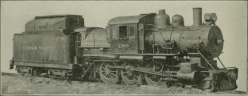
Lehigh Valley Locomotive Equipped with Pulverized Fuel Burning ApparaUib which engages the teeth in the rack on the lied. The tail-stock spindle is moved by a bandw-heel which is placed con-venient to the carriage. A huge steady rest is providedwith every machine. The bed is ribbed throughout with box sections and isfitted with a rack down a center rib which engages a pawlon the tailstock, as a result removing the thrust of a reduce from theclamps of the tail: lock direct to the bed of the lathe. Thetotal weight of the machine is 150.000 lb. pairs and driven by a variable speed inclosed marine typetwo-cylinder double acting reciprocating engine. The fanfor blowing the coal into the locomotive firebox is driven bya steam turbine. The turbine fan supplies approximately15 to 20 per cent of the air required for combustion, the restbeing drawn in by the action of the exhaust by means of theopenings in the firebox and in the burner correct. The four feeders operating in pairs avoid the fuel fromarchin

Note About Images
Please note that these images are extracted from scanned page pictures that might have been digitally enhanced for readability – coloration and appearance of these illustrations may possibly not completely resemble the original operate.

Image from web page 102 of “Les raisons des forces mouuantes auec diuerses machines tant vtilles que plaisantes aus quelles sont adioints plusieurs desseings de grotes et fontaines” (1615)
machining engineering
Image by World wide web Archive Book Photos
Identifier: gri_c00033125008477123
Title: Les raisons des forces mouuantes auec diuerses machines tant vtilles que plaisantes aus quelles sont adioints plusieurs desseings de grotes et fontaines
Year: 1615 (1610s)
Authors: Caus, Salomon de, d. 1626
Subjects: Mechanical engineering Hydraulic barrel organ Fountains Grottoes (Garden structures)
Publisher: A Francfort, En la boutique de Jan Norton
Contributing Library: Getty Investigation Institute
Digitizing Sponsor: Getty Research Institute

View Book Web page: Book Viewer
About This Book: Catalog Entry
View All Images: All Photos From Book

Click here to view book online to see this illustration in context in a browseable online version of this book.

Text Appearing Just before Image:
A LATKES1LLVST%E ET VERTVEVSE PR[NCI S SE

Text Appearing Right after Image:

Note About Photos
Please note that these images are extracted from scanned page images that may possibly have been digitally enhanced for readability – coloration and appearance of these illustrations might not perfectly resemble the original work.

Image from web page 324 of “Railway and locomotive engineering : a sensible journal of railway motive power and rolling stock” (1901)
machining engineering
Image by World wide web Archive Book Images
Identifier: railwaylocomotiv19newy
Title: Railway and locomotive engineering : a practical journal of railway motive power and rolling stock
Year: 1901 (1900s)
Authors:
Subjects: Railroads Locomotives
Publisher: New York : A. Sinclair Co
Contributing Library: Carnegie Library of Pittsburgh
Digitizing Sponsor: Lyrasis Members and Sloan Foundation

View Book Page: Book Viewer
About This Book: Catalog Entry
View All Pictures: All Photos From Book

Click here to view book on the internet to see this illustration in context in a browseable on-line version of this book.

Text Appearing Prior to Image:
aggregate railway mileage in the Pro-vince is 1,174 miles. There were 48 newiron bridges constructed in 1905 and iiS othersare beneath construction. The totalamount expended on roadways andbridges was over ,000. July, igo6. RAILWAY AND LOCOMOTIVE ENGINEERING 313 Historic Locomotive.By the courtesy of the PennsylvaniaLines, and specifically as a outcome of theinterest shown by Mr. D. F. Crawford,common superintendent of motive power,Purdue University, at Lafayette, Ind.,has been able to add a machine of morethan passing interest to its collectionof historic locomotives. This most recent ac-quisition, which is the sixth loconintivc versity. This engine, when place to perform,and with plain wheels, performed a serv-ice which had previously involved theuse of gears. It was in reality a most ex-cellent adaptation of the means to anend, the significance of which becomesgieater when it is remembered that itwas place in service in i868. A matter which lends interest to thegiving of this loconiotivc to Purdue Uni-

Text Appearing Soon after Image:
FIG. I. TANK LOCOMOTIVt REUBEN WELLS, FORMEKLV l)N J., M. 6t I. R. R. to take its place in the Purdue museum,is the Reuben Wells, which was builtin 1868 by what was then the Jefferson-ville, Madison &amp Indianapolis Railway,for use on the Madison incline. Its ap-pearance when new is shown in Fig. i.It was remodeled somewhat not too long ago, therear end of the frame possessing been cutoflf, the number of axles decreased fromfive to four, and a saddle tank placedover the boiler. The engine as it nowappears is shown in Fig. two. This engine has been employed in the im-mediate vicinity of the city of Madison,Ind. Located upon the Ohio river andsurrounded on the east, west and northby hills increasing to a height of more than 400 ft.,Madison was easily accessible from thewater, but the steep hills on all of theroads leading away from the town madeit challenging to distribute merchandise tothe interior. After a extended period of dis-cussion the construction of a railroadwas lastly undertaken. The initial por-tion of th

Note About Images
Please note that these images are extracted from scanned page photos that might have been digitally enhanced for readability – coloration and look of these illustrations may not completely resemble the original operate.

Mechanical Press

Mechanical Press

A machine press, commonly shortened to press, is a machine tool that alterations the shape of a operate piece. A mechanical press is a device designed to apply quite high force to kind, shape, or reduce supplies, to compress solids, or to extract liquids. Mechanical presses range in size from very modest units that are operated by hand, to massive powered industrial units used in manufacturing and assembly line applications. For example, a basic hand press can be employed to take away a bearing from a machine assembly, or a huge press might be used to stamp sheet metal into the curved shapes employed to construct automobile bodies.

An industrial mechanical press is generally utilized for shearing, bending, or forming sheet metal. It usually consists of a structural frame, reduce stationary base, and an upper ram that moves along a vertical axis to apply a force. The component that moves along the axis and applies the force is known as the ram. There are different frame styles and mechanical configurations for the ram, to meet the functional needs of the press.

There are different mechanisms to generate the force employed in a mechanical press. A hydraulic press makes use of 1 or more cylinders, and fluid at really high pressure, to move a cylinder piston and generate the force. Pneumatic presses are comparable to hydraulic presses, but use pressurized air versus fluid. A mechanical press is powered by an electric motor that drives a massive flywheel, crank, and clutch. A servo-driven mechanical press employs higher precision motors to replace the flywheel, and permits greater control of force by means of the complete cycle of the ram.

The quantity of force that a mechanical press can generate is identified as its capacity. Industrial presses are manufactured in a wide assortment of sizes and capacities, ranging from less that 1 ton to ten,000 tons or far more. Mechanical presses used in industrial applications frequently apply a number of tons of force to the objects being formed.

A die is frequently utilized in a mechanical press that is shaping, punching, or trimming a material. The die is mounted to the base of the press and has a profile that matches the shape of the portion being formed. The die gives the cutting surfaces, and a recessed space for the stamped or punched component to fall into.

There are numerous sorts of mechanical presses accessible to suit a assortment of applications. Widespread industrial uses for a mechanical press contain punching, which creates an open hole in sheet metal by removing an internal section of the material stamping, which types sheet metal into a helpful shape and bending, which shapes sheet metal around a straight axis. Other utilizes contain extracting liquids, such as oil extraction from olives for creating olive oil and compressing solids, like the mechanical presses employed to crush vehicles in automotive scrap yards.

The author is connected with IPFonline

http://www.ipfonline.com is India’s No. 1 Industrial Item Finder. The portal is a veritable storehouse of details on industrial products/solutions.

Cool Mechanical Engineering China photos

Cool Mechanical Engineering China photos

A couple of nice mechanical engineering china images I found:

Image from web page 615 of “Railway mechanical engineer” (1916)
mechanical engineering china
Image by Net Archive Book Pictures
Identifier: railwaymechanica95newy
Title: Railway mechanical engineer
Year: 1916 (1910s)
Authors:
Subjects: Railroad engineering Engineering Railroads Railroad vehicles
Publisher: New York, N.Y. : Simmons-Boardman Pub. Co
Contributing Library: Carnegie Library of Pittsburgh
Digitizing Sponsor: Lyrasis Members and Sloan Foundation

View Book Page: Book Viewer
About This Book: Catalog Entry
View All Pictures: All Pictures From Book

Click right here to view book on the internet to see this illustration in context in a browseable online version of this book.

Text Appearing Just before Image:
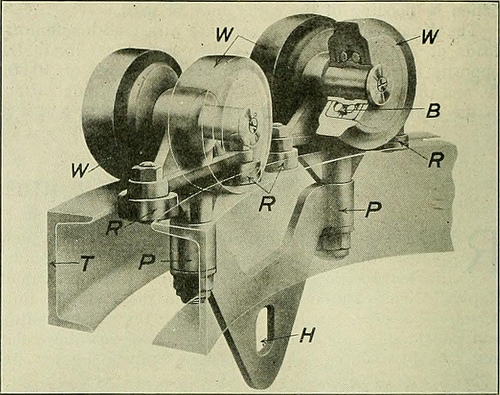
s into an open freightcar or automobile truck. The method can also be readilywired ought to an electric hoist be desired in spot of chainfalls. The track is built and shipped and can be erected assingle units, thus drastically lowering the price of erection. Specific two-wheel, four-wheel, or eight-wheel trolleys are supplied,the four-wheel type being illustrated in Fig. 2. There are ball-bearing wheels W and guide rollers R which run betweenthe toes of the channels, practically eliminating friction andmaking it difficult for the wheels to bind against the track ,&ampmtm WS^J! JB49JP ^five | wzw m m Fig. 1—View of Overhead Trolley Method with Universal Switches when rounding the curves. Carbonized steel ball bearingsare shown at B, pivots at P and the hoist connection at H.The trolley runs on the level leading of the channel tracks and is designed to swing in the identical 18 in. radius curves. Thefact that this track is built from standard rolled channelsor can be built from I-beam sections exactly where long spans and

Text Appearing After Image:
Fig. 2—Phantom View of Short Turn Trolley greater strength is necessary, tends to make it straightforward to obtain fromlocal stocks and less complicated to erect. The operation of this systemlightens the function and makes it considerably a lot more easy and favorablefor the workmen handling material, thereby decreasing laborturnover and rising the efficiency of unskilled labor.The system is being manufactured and sold by the WhitingCorporation, Harvey, 111. Unique Hydraulic Driving Wheel Press THE Hydraulic Press Manufacturing Firm, MountGilead, Ohio, designed and built the particular hydraulicpress, illustrated, which was lately sold by the Mc-Carter Cooper Business, New York, to the Compagnie Gen-eral De Chemins De Fer &amp Tramways en Chine, Pekin,China. This press is employed for forcing driving wheels on or off amongst strain bars is 84 in. and in between ram and resistancehead is 108 in. maximum. This may possibly be decreased to 78 in.by moving the resistance head, which is mounted on wheels.The press is also equipped with a belt

Note About Photos
Please note that these photos are extracted from scanned page photos that might have been digitally enhanced for readability – coloration and appearance of these illustrations may possibly not perfectly resemble the original perform.

Image from web page 67 of “Railway mechanical engineer” (1916)
mechanical engineering china
Image by World wide web Archive Book Pictures
Identifier: railwaymechanica93newy
Title: Railway mechanical engineer
Year: 1916 (1910s)
Authors:
Subjects: Railroad engineering Engineering Railroads Railroad automobiles
Publisher: New York, N.Y. : Simmons-Boardman Pub. Co
Contributing Library: Carnegie Library of Pittsburgh
Digitizing Sponsor: Lyrasis Members and Sloan Foundation

View Book Page: Book Viewer
About This Book: Catalog Entry
View All Images: All Images From Book

Click right here to view book on the web to see this illustration in context in a browseable on the internet version of this book.

Text Appearing Before Image:
ult, nowadays the Continental—European—design of locomotive is predominant in China.On some of the lines, notably these beneath English and,hitherto, German influence, not a locomotive other than thosebuilt in accordance with the prevailing design frequent tothe nation financing the railway was bought or even con-sidered, either for initial or sub.sequent equipment—at leastup to the time of the outbreak of the war. Only in the caseof the Chinese financed and operated railway have Ameri-can builders been offered a cost-free hand, with the result that anAmerican design and style was adopted, and a thorough standardiza-tion of energy effected. Out of the 638 locomotives in ser-vice on all lines at that time only 15 five/2 per cent had been ofAmerican desi.gn and manufacture and on the Engli.sh,Belgian, and French lines, which operated at that time 365locomotives, or around 60 per cent of the total, onlveight, or approximately 2.2 per cent had been of American de-sign and manufacture.—Eastern Engineering.

Text Appearing Soon after Image:
THE BLOMQUIST-ECK HORIZONTALBORING MILL The operating efficiency of any horizontal mill and drilldepends entirely upon its potential to operate upon all classesof work at the highest speeds and coarsest feeds practicable,and at all occasions to generate a completed product of dependableaccuracy. The Blomquist-Eck Machine Firm, Cleve-land, Ohio, in designing its new horizontal boring mill, hasdeveloped these points to a higher degree by combiningrigidity, accuracy, a suitable range of selective speeds and

Note About Pictures
Please note that these pictures are extracted from scanned page photos that may have been digitally enhanced for readability – coloration and look of these illustrations may not completely resemble the original work.