Cool Metal Components China images

Cool Metal Components China images

Check out these metal components china images:

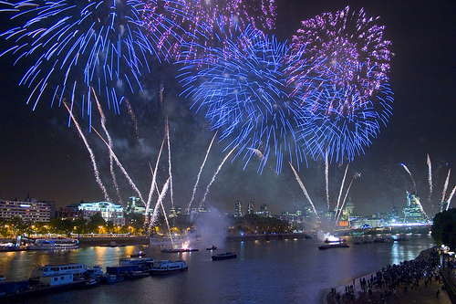
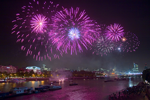
Thames Festival Weekend Finale Fireworks
metal parts china
Image by Dominic’s pics
Component of a Set / Virtual Firework Display Slideshow documenting the firework show that marked the end of the &quotthe mayor’s&quot Thames Festival in London on the evening of Sunday September 11th 2011.

The display was presented by Pains Fireworks.

A delay in the start off of the display from the scheduled time was attributed by the crowds to incompetence by &quotBumbling Boris&quot Johnson – the London Mayor – element of the British patrician &quotlimited liability&quot ruling class. &quotI’m in charge, but if something goes incorrect, somebody else will be sacked…&quot

Like the intense audio dynamic range of Taiko or Samba drumming, it is not genuinely feasible to record the visual brilliance of fireworks with a camera. You have to expertise firework displays reside, in person. These photos have been taken at the slowest sensor speed (ISO 100), maximum aperture (to minimise diffraction &quotglare&quot effects) and with a selection of exposure instances ranging from about .five to two seconds. The intense light triggered some &quotbleaching&quot of the paths of the lights, and so the colours have been enriched if Photoshop. (In retrospect I may have utilized a slightly smaller sized aperture.)In addition, the river and land areas have been selectively lightened in Photoshop. Fortuitously, a gentle breeze brought on the smoke to drift eastwards, away from my vantage point on Waterloo Bridge, so the view of the fireworks was comparatively unobstructed by smoke.

Fireworks date from at least the 7th century in China. The colours are believed to have been traditional incandescent &quotblack physique&quot bonfire colours: red, orange, yellow and white. (It is theoretically achievable to generate pale blue just by heating, but this requires impracticably high temperatures. It is not feasible to heat one thing to &quotgreen hot&quot or &quotpurple hot&quot.) It is believed that from about 1830 in Italy metal salts have been introduced to create a wider, richer hued, spectrum of colours by chemical luminescence. This strategy can be problematic, as it can be difficult to develop stable, practical, chemical compositions. It has been recommended that some shades of green are still challenging to attain.

See also:

Fireworks [Wikipedia]
Firework Colours [The chemistry of Fireworks by Reema Gondhia, Imperial College]
History of fireworks [Pyro Universe]

Thames Festival Finale Fireworks
metal parts china
Image by Dominic’s pics
Component of a Set / Virtual Firework Display Slideshow documenting the firework show that marked the end of the &quotthe mayor’s&quot Thames Festival in London on the evening of Sunday September 11th 2011.

The show was presented by Pains Fireworks.

A delay in the commence of the display from the scheduled time was attributed by the crowds to incompetence by &quotBumbling Boris&quot Johnson – the London Mayor – part of the British patrician &quotlimited liability&quot ruling class. &quotI’m in charge, but if something goes wrong, somebody else will be sacked…&quot

Like the extreme audio dynamic range of Taiko or Samba drumming, it is not actually attainable to record the visual brilliance of fireworks with a camera. You have to knowledge firework displays reside, in individual. These photos had been taken at the slowest sensor speed (ISO 100), maximum aperture (to minimise diffraction &quotglare&quot effects) and with a selection of exposure occasions ranging from about .five to two seconds. The intense light triggered some &quotbleaching&quot of the paths of the lights, and so the colours have been enriched if Photoshop. (In retrospect I may possibly have used a slightly smaller aperture.)In addition, the river and land places have been selectively lightened in Photoshop. Fortuitously, a gentle breeze triggered the smoke to drift eastwards, away from my vantage point on Waterloo Bridge, so the view of the fireworks was comparatively unobstructed by smoke.

Fireworks date from at least the 7th century in China. The colours are believed to have been conventional incandescent &quotblack physique&quot bonfire colours: red, orange, yellow and white. (It is theoretically feasible to create pale blue just by heating, but this needs impracticably high temperatures. It is not achievable to heat one thing to &quotgreen hot&quot or &quotpurple hot&quot.) It is believed that from about 1830 in Italy metal salts were introduced to create a wider, richer hued, spectrum of colours by chemical luminescence. This method can be problematic, as it can be difficult to produce steady, sensible, chemical compositions. It has been suggested that some shades of green are still tough to accomplish.

See also:

Fireworks [Wikipedia]
Firework Colours [The chemistry of Fireworks by Reema Gondhia, Imperial College]
History of fireworks [Pyro Universe]

Nice Prototype Engineering images

Nice Prototype Engineering images

A couple of nice prototype engineering pictures I discovered:

Japanese Tank Sort 95 Ha-Gō (九五式軽戦車 ハ号 Kyugoshiki keisensha Ha-Gō). 1935. Японский танк Тип 95 “Ха-Го”.
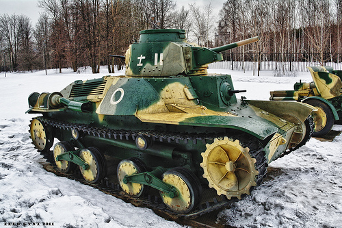
prototype engineering
Image by Peer.Gynt
Poklonnaya Gora WWII Museum. Moscow.
Поклонная гора. Москва.

Specifications
Weight – 7,400 kilograms
Length – four.38 m
Width – 2.06 meters
Height- two.18 meters
Crew – 3

Main armament Type 94 37 mm gun
Secondary armament Type 91 six.5 mm machine gun or 2 x Type 97 7.7 mm machine gun
Engine Mitsubishi NVD 6120 air-cooled diesel 120 hp (89 kW)
Suspension Bell crank
Operational range250 kilometers
Speed 45 km/h (road)

The Kind 95 Ha-Gō (九五式軽戦車 ハ号 Kyugoshiki keisensha Ha-Gō?) (also recognized as the Type 97 Ke-Go) was a light tank employed by the Imperial Japanese Army in combat operations of the Second Sino-Japanese War and the Second Globe War. Despite the fact that it was quite slow for a light tank, it proved sufficient against opposing infantry in campaigns in Manchuria and China, as the Chinese National Revolutionary Army had very handful of tanks or anti-tank weapons to oppose them. However, the Kind 95 lacked the armor or armament of contemporary Allied tanks, and was regarded as obsolete by the begin of World War II. Much more than 2,000 units were produced. It was also employed by Imperial Japanese Navy SNLF detachments in Pacific locations during conflict.
History and improvement

From early 1930s, the Japanese army began experimenting on a mechanized warfare unit combining infantry with tanks. Nevertheless, the Variety 89 Medium tank could not maintain pace with the motorized infantry, which could move at 40 km/h by truck. To resolve this issue, the Army Technical Bureau proposed a new light tank at 40 km/h speed and began development in 1933. The prototype of the new tank was completed in 1934 at the Army’s Sagami Arsenal. It was a higher-speed and lightly-armored tank comparable to the British cruiser tank or Soviet BT tank. Its code name was &quotHa-Gō&quot (ハ号) designated that it was the &quotthird variety&quot of tank developed.[three]

In 1935, a meeting was held at the Army Technical Bureau, at which time, the Sort 95 was presented as a potential principal battle tank for mechanized infantry units. The infantry had issues that the armor was not thick sufficient for sufficient infantry support nonetheless, the cavalry indicated that the improved speed and armaments compensated for this thin armor. In the end, the infantry agreed, as the Kind 95 was nevertheless superior to the only offered option, which was the armored car.

Production was started in 1935 by Mitsubishi Heavy Industries. By 1939, 100 units had been constructed. Mitsubishi would go on to create a total of 853 in their personal factories, with yet another 1250 units constructed by the Sagami Arsenal, Hitachi Industries, Niigata Tekkoshō, Kobe Seikoshō, and Kokura Arsenal.[two]

Type 95 Ha-Go tanks in New Britain following the Japanese surrender

Variety 95 on show at the United States Army Ordnance Museum, front view

Correct side view.

Type 95 at Tarawa

The Type 95 was a major improvement more than the Japanese Army’s prior light tanks and tankettes, but was soon involved in an intensive plan to make enhanced variants such as the Manshū model (Type M), the Ha-Gō’s direct descendant. Sort M was technically identical but created for use in the Kwantung Army’s tank schools in Manchukuo and it was planned to be provided in far far more numbers to future Manchukuo Imperial Army armored units and was projected to be manufactured in that country.

One more improvement was the Kind 98 Ke-Ni light tank that entered production in 1942 of which 200 autos had been constructed. This derivitative was better armored and carried an armament comprising one particular Variety 100 37 mm gun and two 7.7 mm machine guns.

The Kind 95 also served as the basis of the Type 2 Ka-Mi amphibious tank which gave good service in Japan’s early campaigns of Globe War II.

[edit]
Design and style

The Type 95 was a 7.4-ton vehicle with a complement of 3 crewmen (normally a commander/gunner/loader, mechanic/bow machine gunner, and a driver).

The main armament was one particular Sort 94 37 mm Tank Gun with 37 mm caliber, barrel length of 1.3585 meters (L36.7) (early model), 1.358 meters (L36.7) (late model), el angle of fire -15 to +20 degrees (early model), -15 to +20 degrees (late model), AZ angle of fire of 20 degrees (early model) 20 degrees (late model), muzzle velocity: 600 m/s (early model), 700 m/s (late model), penetration: 45 mm/300 m (early model) 25 mm/500 m (late model) utilized by the Kind 95 Light Tank. The commander was accountable for loading, aiming, and firing the primary gun, The Kind 95 tank carried two sorts of ammunition, Kind 94 high-explosive and Type 94 armor-piercing.

Secondary armament consisted as two Type 91 six.5mm machine guns, 1 mounted in the hull and the other in the turret facing to the rear. Trial use in Manchukuo and China confirmed that much better armament was desirable and the 6.5mm machine guns had been exchanged for more powerful 7.7mm Sort 97 light machine guns on the appropriate hand side, for use by the currently overworked commander/gunner in 1941. The original Type 94 major gun was also replaced with a Kind 98 weapon of the identical caliber but with a larger muzzle velocity.

The hand-operated turret was little and very cramped for even the one particular crewman normally located there (the commander), and was only becoming able to rotate in a 45 degree forward arc, leaving the back to be covered by the rear-facing machine gun which failed to compensate for this significant disadvantage.

The most characteristic feature of the Kind 95 tank was its simple suspension system. The tracks had been driven through the front sprocket. Two bogie wheels have been suspended on a single bell crank with two bell cranks per side. There had been two return wheels. The suspension had troubles early on with a tendency to pitch so badly on rough ground that the crew at times located it impossible to drive at any speed, and so it was modified with a brace to connect the pairs of bogies. Despite this, the tank continued to give its users a rough ride across any uneven ground, and was provided with an interior layer of asbestos, valuable in reducing interior heat and defending the crew from injury when the tank moved at high speed across rough terrain.[3]

This initial production models employed one particular 110 hp (82 kW) Mitsubishi air cooled diesel engine with a leading speed of 25 mph (40 km/h). This was the exact same engine that equipped the Kind 89 I-Go medium tank. Later the much more potent engine Mitsubishi NVD 6120 with 120 hp (89.five kW) was installed.[3] Some Variety 95 had been fitted with two reflectors in the front of the automobile for night operations.

[edit]
Variants

Type 95 tank in Bovington tank museum, Dorset

Type 95 on show at the Battery Randolf US Army Museum, Honolulu, top rear view

Kind 95 Ha-Go tanks destroyed by an Australian two pounder gun in the Battle of Muar

A single of six Ha-Go tanks destroyed by an Australian 2 pounder gun in the Battle of Muar. The escaping crew had been killed by allied infantry covering the artillery
Kind three Ke-Ri
This was a proposed model with a Type 97 57 mm gun as the principal armament. This design in no way got previous testing in 1943.
Variety 4 Ke-Nu
The Variety 4 Ke-Nu was intended to address one of the most widespread complaints about the Kind 95 from its customers – the cramped turret. The current Sort 95 turret was replaced by the turret of a Kind 97 Medium tank for more space. About 100 units had been made.
Sort 95 Manshū
The Kind 95 Manshū was an operational and training tank derived from and really comparable to the Kind 95 Ha-Gō. These tanks were detached to Manchukuo and belonged to the instruction unit of the Kwantung Army tank college.
Variety 95 &quotTa-Se&quot Anti-Aircraft Tank
An experimental car known as &quotTa-Se&quot was built in November 1941, utilizing the chassis of Sort 95 Ha-Gō with a 20 mm anti-aircraft gun taken from the Type 98 20 mm anti-aircraft gun. Another version utilised a Type two 20 mm anti-aircraft gun. Neither model went into production.
Sort 2 Ka-Mi Amphibious Tank
This was the 1st amphibious tank created in Japan, and was intended for use by the Navy’s SNLF. The pontoons could be detached after landing by a fourth crewman from inside the tank. The chassis was primarily based on the Variety 95 Light Tank. The Type 2 Ka-Mi was encountered by the United States Marine Corps in the Marshall Islands and Mariana Islands, especially on Guam, exactly where it was utilized in static defense positions.
Variety 95 &quotRi-Ki&quot Crane Car
The Sort 95 Ri-Ki was an engineering car for field functions. It had a 3-ton 4.five meter boomed crane.
120 mm self-propelled gun &quotHo-To&quot
The Kind 95 Ho-To was a Sort 38 120 mm howitzer mounted on the Sort 95 Ha-Go chassis. The gun was low-velocity but the HEAT shell enabled it to destroy the American M4 Sherman tank. This self-propelled gun was developed along with the Ho-Ru self-propelled gun.
Sort five Ho-Ru 47 mm self-propelled gun
The Ho-Ru was a light tank destroyer equivalent to the German Hetzer. The improvement of the Sort five Ho-Ru started in February 1945. The Variety five Ho-Ru utilized the chassis of the Variety 95 Light Tank, but its suspension was enlarged to 350 mm track hyperlink width. The wheel guide pins had been set in two rows to hold a road wheel among them. The sprocket of the driving wheel was the grating variety to gear with the wheel guide pins like on the Soviet T-34. It was armed with one particular 47 mm primary gun.
Variety 98 Ke-Ni light tank
This final modification was somewhat lighter than the original Variety 95, even with its heavier (.62 inch) armor. It entered production in 1942, but only about 200 were manufactured.

[edit]
Combat history

When the Kind 95 entered service in 1935 it was a capable machine and comparable to any contemporary light tank in the globe. It was the very best car of its category offered to the Japanese forces in any numbers from the 1930s to World War II, and was utilised mostly to assistance infantry or as cavalry reconnaissance and, to a lesser extent, as raiding cars. It could compete with the American M3 light tanks on the Philippines, while the British had really couple of tanks of any kind in Malaya or Burma in December 1941. [4]

The Variety 95 Ha-Gō proved moderately successful for the duration of the early campaigns of late 1941 and early 1942, when Japanese forces overran British Malaya and seized the fortress city of Singapore. A single important to the Japanese good results in Malaya was the unexpected presence of their tanks in places exactly where the British did not believe tanks could be employed. The wet jungle terrain did not turn out to be an obstacle twelve Kind 95s took part in the attack which broke the Jitra line on 11 December 1941.

The very first tank-vs-tank battles of the war was on 22 December 1941 for the duration of the Japanese invasion of the Philippines. Variety 95s of the 4th Tank Regiment clashed with M3s of the American 192nd Tank Battalion. Both tanks had been armed with a 37 mm gun, and the M3 was better armored nevertheless, the inexperienced American commanders failed to make good use of their tanks.

Two Variety 95 tanks were deployed to assistance the Japanese landing at Milne Bay, late August 1942. Initially, the tanks proved successful against the lightly armed Australian infantry, whose ‘sticky bombs’ failed to stick due to the humidity. Even though the tanks had proved trustworthy in the tropical circumstances of Malaya, they could not deal with the volume of mud brought on by intense, virtually everyday rainfall at Milne Bay. Each tanks had been bogged down and abandoned a handful of days right after the landing.

The Sort 95 very first began to show its vulnerability in the course of later battles against British/Commonwealth forces, where the tank’s 37mm gun could not penetrate the armor of the British Matilda tanks which have been deployed against them. The thin armor of the Variety 95 made it increasingly vulnerable as Allied forces realized that common infantry weapons have been capable of penetrating the minimal armor about the engine block, and even its thickest armor could not withstand anything above rifle caliber. Its firepower was insufficient to take on other tanks such as the medium M4 Sherman or the M3 Stuart light tanks. [4]

As the tide of the war turned against Japan, the Sort 95s had been escalating expended in banzai charges or were dug-in as pillboxes in static defense positions in the Japanese-occupied islands. During the Battle of Tarawa, seven entrenched Type 95th opposed American landings. More have been destroyed on Parry Island and on Eniwetok. On Saipan, Sort 95s attacked the American Marine beachhead on 16 June 1944 and much more were utilized in the largest tank battle in the Pacific the following day.

In the Battle of Guam on 21 July, ten Kind 95 had been lost to bazooka fire or M4 tanks. Seven a lot more had been destroyed on Tinian on 24 July, and 15 much more on Battle of Peleliu on 15 September. Likewise, in the Philippines, at least ten Variety 95s have been destroyed in various engagements on Leyte, and yet another 19 on Luzon. At the Battle of Okinawa, 13 Type 95s and 14 Type 97 Shihoto medium tanks of the 27th Tank Regiment faced 800 American tanks.

When the war ended hundreds of Type 95s have been left in China. They had been used for the duration of the Chinese Civil War and by the People’s Liberation Army of the People’s Republic of China throughout the Korean War.

Soviet Higher-Speed Tank BT-two. Советский быстроходный танк БТ-two.
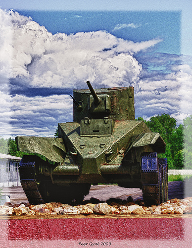
prototype engineering
Image by Peer.Gynt
The BT tanks (Russian: Быстроходный танк (БТ), Bystrokhodny tank, lit. &quotfast tank&quot or &quothigh-speed tank&quot) were a series of Soviet cavalry tanks produced in big numbers in between 1932 and 1941. They have been lightly armoured, but reasonably nicely-armed for their time, and had the best mobility of all modern tanks of the planet. The BT tanks have been known by the nickname Betka from the acronym, or its diminutive Betushka.

The direct successor of the BT tanks would be the well-known T-34 medium tank, introduced in 1940, which would replace all of the Soviet quick tanks, infantry tanks, and medium tanks in service.
Design and style

The BT tanks had been &quotconvertible tanks&quot. This was a function made by J. Walter Christie to decrease put on of the unreliable tank tracks of the 1930s. In about thirty minutes the crew could get rid of the tracks and engage a chain drive to the rearmost road wheel on each side, enabling the tank to travel at very higher speeds on roads. In wheeled mode the tank was steered by pivoting the front road wheels. Even so, Soviet tank forces soon discovered the convertible selection of little practical use in a country with handful of paved roads, and it consumed space and added needless complexity and weight. The feature was dropped from later Soviet styles.

Christie, a race vehicle mechanic[citation needed] from New Jersey, had tried unsuccessfully to convince the U.S. Army Ordnance Bureau to adopt his Christie tank style. In 1930, Soviet agents at Amtorg, ostensibly a Soviet trade organization, utilized their New York political contacts to persuade U.S. military and civilian officials to give plans and specifications of the Christie tank to the Soviet Union. At least two of Christie’s M1931 tanks (without having turrets) had been later bought in the United States and sent to the Soviet Union below false documentation in which they have been described as &quotagricultural tractors.&quot[citation necessary] Both tanks were effectively delivered to the Kharkov Komintern Locomotive Plant (KhPZ). The original Christie tanks have been designated quick tanks by the Soviets, abbreviated BT (later referred to as BT-1). Based both on them and on previously obtained plans, three unarmed BT-two prototypes have been completed in October 1931 and mass production started in 1932. Most BT-2s have been equipped with a 37 mm gun and a machine gun, but shortages of 37 mm guns led to some early examples getting fitted with three machine guns.

The sloping front hull (glacis plate) armor design and style of the Christie M1931 prototype was retained in later Soviet tank hull styles, later adopted for side armor as properly.

The BT-five and later models were equipped with a 45 mm gun.

BT-1: Christie prototype with no turret.
BT-two Model 1932: M-five-400 engine (copy of U.S. Liberty engine), 3 modifications of turret produced: with single 37 mm gun 37 mm gun and 1 DT machine gun twin DP machine guns mount and a single machine gun. In late 1932 modified to BT-three but created beneath identical designation.
BT-3: exact same as BT-2, developed according to metric program (rather of Imperial system as employed for BT-two). In official documentation referred to as BT-2.
BT-four: was a design and style with welded hull and minor modifications in the suspension. 3 prototypes made (with partially riveted hull)
BT-five: bigger cylindrical turret, 45 mm gun, coaxial DT machine gun. BT-five Model 1933: new turret with twin hatches and larger bustle.
BT-5PKh: snorkelling variant (prototypes only).
BT-5A: artillery assistance version with 76.two mm howitzer (few made).
BT-five flamethrower tank: (prototypes only).
PT-1A: amphibious variant with new hull (couple of made).

BT-7 Model 1935: welded hull, redesigned hull front, new Mikulin M-17T engine (licensed copy of a BMW engine), enclosed muffler. BT-7 Model 1937: new turret with sloping armour.
BT-7TU: command version, with whip antenna rather of earlier frame antenna.
BT-7A: artillery assistance version with 76.2 mm howitzer.
OP-7: flame-thrower version with external fuel panniers (prototype only).

BT-7M[3] (1938, prototypes designated A-eight sometimes referred to as BT-8): new V-two diesel engine replacing earlier gasoline engines, 3 DT machine guns: coaxial, in P-40 AA mount on roof and in a ball-mount on turret rear.
BT-42: Finnish assault gun captured BT-7s had been equipped with British 114 mm howitzers.
BT-43: Finnish armoured personnel carrier captured BT-7s equipped with troop accommodation.
BT-IS: Prototype/proof-of-idea platform with heavily sloped armor forerunner of the armor style on the T-34.
BT-SW-2 Cherepakha (&quotturtle&quot): Yet another prototype, which took the armour sloping to an intense.
A-20: Prototype for a new BT tank, with 20 mm armour, 45mm gun, model V-2 diesel engine, and 8×6-wheel convertible drive. Lost out in trials to the A-32, which was further enhanced and produced as the T-34 medium tank.
TTBT-five, TTBT-7: teletanks, remote-controlled tanks.

Combat history

BT tanks saw service in the Spanish Civil War, Battle of Khalkhin Gol (Nomonhan), the Winter War in Finland, the Polish campaign, and in the whole Globe War II.
They first saw action in the Spanish Civil War. A battalion of BT-5s fought on the Republican side, and their 45 mm guns could easily knock out the opposing German and Italian light tanks
Battle of Khalkhin Gol (Nomonhan)
See also: Soviet–Japanese Border Wars
For the duration of the Battles of Khalkhin Gol (also identified as the Nomonhan Incident), which lasted from May possibly to September in 1939, BT tanks have been simply attacked by Japanese &quotclose quarter&quot teams (tank killer squads) which had been armed with petrol bottles (later named &quotMolotov Cocktails&quot). The Soviet BT-five and BT-7 light tanks, which had been operating in temperatures higher than 100F on the Mongolian plains, effortlessly caught fire when a molotov cocktail ignited their gasoline engines.Basic Georgy Zhukov produced it a single of his &quotpoints&quot when briefing Joseph Stalin, that his &quot…BT tanks were a bit fireprone….&quot Conversely, numerous Japanese tankers held the Soviet 45mm anti-tank/tank guns in high esteem, noting, &quot…no sooner did they see the flash from a Russian gun, than they’d notice a hole in their tank, adding that the Soviet gunners were accurate as well!&quot
Right after the Khalkhin Gol War in 1939, the Soviet military had broken into two camps one particular side was represented by Spanish Civil War veterans Common P. V. Rychagov of the Soviet Air Force, Soviet armour expert Common Dimitry Pavlov, and Stalin’s favourite, Marshal Grigory Kulik, Chief of Artillery Administration.[16] The other side consisted of the Khalkhin Gol veterans led by Generals Zhukov and G.P. Kravchenko of the Soviet Air Force.[17] Beneath this cloud of division, the lessons of Russia’s &quotfirst real war on a huge scale using tanks, artillery, and airplanes&quot at Nomonhan (Khalkhin Gol) went unheeded. Consequently, for the duration of the Finland War (Winter War) the BT-two and BT-5 tanks were less profitable, and it took the Soviet Union 3 and a half months, and more than a million males to do what Zhukov did in just ten days at Nomonhan.
Following the German war broke out, the Spanish Civil War faction fell in disfavor, with Marshal Kulik in specific getting court-martialed and demoted. Gen. Zhukov and the majority of his surviving Nomonhan veterans were appointed to commands throughout European Russia, in time to engage the German armies.
Globe War II
Throughout the Second World War, BT-5 and BT-7 tanks have been utilized in the 1939 Soviet invasion of Poland, and in large numbers in the battles of 1941 – in the course of which thousands had been abandoned or destroyed. A handful of remained in use in 1942, but were uncommon following that time. The Red Army planned to replace the BT tank series with the T-34, and had just begun doing so when the German invasion (Operation Barbarossa) took location.
In the course of the final weeks of World War II, a significant quantity of BT-7 tanks took element in the invasion of Japanese-occupied Manchuria, in August 1945. This was the last combat action of BT tanks.
Technical legacy

The BT tank series was several, forming the cavalry tank arm of the Red Army in the 1930s, and had significantly better mobility than other contemporary tank designs. For these reasons, there had been several experiments and derivatives of the design and style, largely carried out at the KhPZ factory in Kharkov.
The most important legacy of the BT tank was the T-34 medium tank, arguably the most essential tank of the entire World War II. In 1937, a new design and style team was formed at the KhPZ to create the subsequent generation of BT tanks. Initially, the chief designer was Mikhail Koshkin and, following his death, Morozov. The group constructed two prototypes. The light one particular was called the A-20. The much more heavily armed and armoured BT derivative, the A-32, was a &quotuniversal tank&quot to replace all the T-26 infantry tank, BT cavalry tanks, and the T-28 medium tanks. Such plan was controversial, but issues about tank overall performance beneath the threat of German blitzkrieg led to the approval for production of a nevertheless more heavily-armoured version, the T-34 medium tank.
Along the way, an essential technical development was the BT-IS and BT-SW-2 testbed automobiles, concentrating on sloped armour. This proof-of-concept led straight to the armour layout of the T-34.
BT tank chassis have been also used as the basis for engineering assistance autos and mobility testbeds. A bridgelayer variant had a T-38 turret and launched a bridge across modest gaps. Normal tanks have been fitted as fascine carriers. The RBT-5 hosted a pair of large artillery rocket launchers, a single on every single side of the turret. Many designs for incredibly wide tracks, like, oddly, wooden ‘snowshoes’ had been attempted on BT tanks.
The KBT-7 was a completely modern day armoured command automobile that was in the prototype stage when Planet War II broke out. The design and style was not pursued for the duration of the war.
In the Kiev maneuvers of 1936, foreign military observers have been shown hundreds of BT tanks roll by a reviewing stand. In the audience had been British Army representatives, who returned residence to advocate for use of Christie suspension on British cruiser tanks which they incorporated from the Cruiser Mk III onwards. Interestingly, the pointed shape of the hull front armor on the BT tank also influenced the design of the British Matilda tank.
Cool Precision Engineering Solutions images

Cool Precision Engineering Solutions images

Some cool precision engineering services pictures:

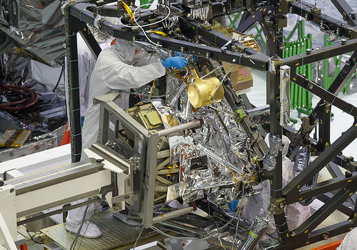
Crucial Science Instrument Installed into Webb Structure
precision engineering services
Image by NASA Goddard Photo and Video
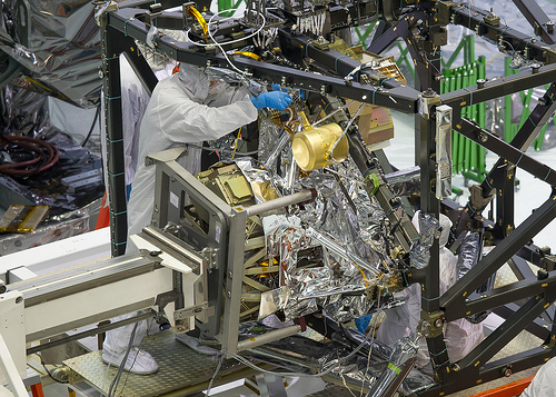
A technician is installing the bolts that will hold the MIRI, or Mid-Infrared Instrument, to the composite Integrated Science Instrument Module (ISIM) structure, or the black frame. The MIRI is attached to a balance beam, known as the Horizontal Integration Tool (HIT), hanging from a precision overhead crane. That is the identical tool that Hubble engineers employed to prepare hardware for its servicing missions.

Photo Credit: NASA/Chris Gunn Text Credit: NASA/Laura Betz

—-

Engineers worked meticulously to implant the James Webb Space Telescope’s Mid-Infrared Instrument into the ISIM, or Integrated Science Instrument Module, in the cleanroom at NASA’s Goddard Space Flight Center in Greenbelt, Md. As the successor to NASA’s Hubble Space Telescope, the Webb telescope will be the most strong space telescope ever constructed. It will observe the most distant objects in the universe, offer pictures of the very first galaxies formed and see unexplored planets about distant stars.

For far more details, visit: www.jwst.nasa.gov

NASA image use policy.

NASA Goddard Space Flight Center enables NASA’s mission by way of 4 scientific endeavors: Earth Science, Heliophysics, Solar Technique Exploration, and Astrophysics. Goddard plays a top role in NASA’s accomplishments by contributing compelling scientific information to advance the Agency’s mission.

Adhere to us on Twitter

Like us on Facebook

Discover us on Instagram

Boeing B-17 – Duxford Airshow Oct 2010
precision engineering services
Image by Feggy Art
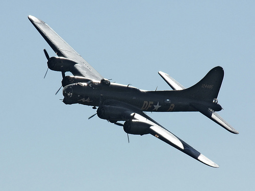
Boeing B-17 at Duxford Airshow October 2010.

The Boeing B-17 Flying Fortress was a four-engine heavy bomber aircraft created in the 1930s for the United States Army Air Corps (USAAC). Competing against Douglas and Martin for a contract to develop 200 bombers, the Boeing entry outperformed each competitors and more than met the Air Corps’ expectations. Despite the fact that Boeing lost the contract simply because the prototype crashed, the Air Corps was so impressed with Boeing’s design that they ordered 13 a lot more B-17s for additional evaluation. From its introduction in 1938, the B-17 Flying Fortress evolved by way of quite a few design advances.

The B-17 was mostly employed by the United States Army Air Forces (USAAF) in the daylight precision strategic bombing campaign of Planet War II against German industrial and military targets. The United States Eighth Air Force primarily based at Thorpe Abbotts airfield in England and the Fifteenth Air Force primarily based in Italy complemented the RAF Bomber Command’s night time area bombing in Operation Pointblank to assist safe air superiority over the cities, factories and battlefields of Western Europe in preparation for Operation Overlord. The B-17 also participated to a lesser extent in the War in the Pacific exactly where it carried out raids against Japanese shipping and airfields.

From its pre-war inception, the USAAC (later USAAF) touted the aircraft as a strategic weapon it was a potent, higher-flying, long-variety bomber that was capable to defend itself, and to return house in spite of in depth battle harm. It swiftly took on mythic proportions, and extensively circulated stories and photographs of B-17s surviving battle harm enhanced its iconic status. With a service ceiling higher than any of its Allied contemporaries, the B-17 established itself as an efficient weapons technique, dropping far more bombs than any other U.S. aircraft in World War II. Of the 1.five million metric tons of bombs dropped on Germany by U.S. aircraft, 640,000 tons have been dropped from B-17s.

General characteristics

•Crew: 10: Pilot, co-pilot, navigator, bombardier/nose gunner, flight engineer-leading turret gunner, radio operator, waist gunners (2), ball turret gunner, tail gunner
•Length: 74 ft 4 in (22.66 m)
•Wingspan: 103 ft 9 in (31.62 m)
•Height: 19 ft 1 in (five.82 m)
•Wing region: 1,420 sq ft (131.92 m2)
•Airfoil: NACA 0018 / NACA 0010
•Aspect ratio: 7.57
•Empty weight: 36,135 lb (16,391 kg)
•Loaded weight: 54,000 lb (24,500 kg)
•Max takeoff weight: 65,500 lb (29,700 kg)
•Powerplant: 4× Wright R-1820-97 Cyclone turbo supercharged radial engines, 1,200 hp (895 kW) each and every

Functionality

•Maximum speed: 287 mph (249 kn, 462 km/h)
•Cruise speed: 182 mph (158 kn, 293 km/h)
•Range: 2,000 mi (1,738 nmi, 3,219 km) with two,700 kg (6,000 lb) bombload
•Service ceiling: 35,600 ft (ten,850 m)
•Rate of climb: 900 ft/min (4.6 m/s)
•Wing loading: 38. lb/sq ft (185.7 kg/m2)
•Power/mass: .089 hp/lb (150 W/kg)

Armament

•Guns: 13 × .50 in (12.7 mm) M2 Browning machine guns in four turrets in dorsal, ventral, nose and tail, 2 in waist positions, 2 beside cockpit and 1 in the reduced dorsal position
•Bombs:
•Short variety missions (&lt400 mi): 8,000 lb (three,600 kg)
•Long variety missions (≈800 mi): 4,500 lb (2,000 kg)
•Overload: 17,600 lb (7,800 kg)

Text and specifications primarily based on Wikipedia write-up beneath the Inventive Commons License for non-profit use.

This is the Boeing B17G-105-VE Flying Fortress 124485 G-BEDF (Memphis Belle)

Cool Prototype Engineering images

Cool Prototype Engineering images

Check out these prototype engineering pictures:

Argonne, KAERI to develop prototype nuclear reactor
prototype engineering
Image by Argonne National Laboratory
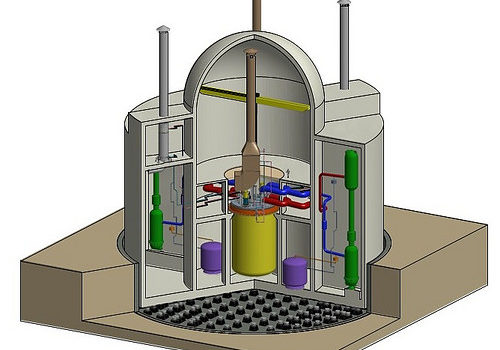
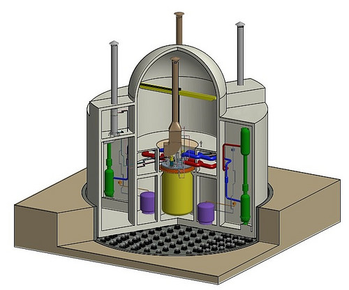
Argonne will support the Korean Atomic Power Investigation Institute’s development of a Prototype Generation-IV Sodium-cooled Quick Reactor that incorporates an innovative metal fuel developed at Argonne. The fuel’s inherent safety prospective was demonstrated in landmark tests performed on the Experimental Breeder Reactor-II. Image credit: KAERI. Study a lot more &raquo

1955 Leyland Bus, Longwell Green Coach Works
prototype engineering
Image by brizzle born and bred
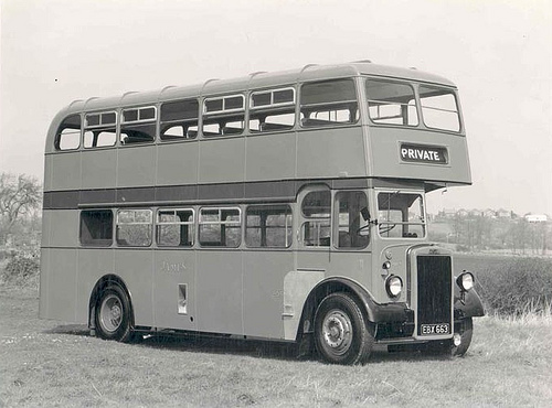
1955 Leyland Double Decker Bus at Longwell Green Coach Operates BS30.

W.J. Bence &amp Sons – Pioneer’s of Early Motor Transport.

New Book About Bristol’s buses

When the very first double-decker buses left the factory and took to the roads, they encountered a key problem – they have been just too high to get under most railway bridges.

One particular answer, perhaps the most obvious, was to reduced the ceiling on the upper deck.

But even though the engineers managed to minimize the height by about a foot or so, the bench-sort seating arrangements upstairs and encroachment into the reduce deck proved unworkable.

There just wasn’t sufficient space for the passengers to sit comfortably.

The Bristol Tramways and Carriage Firm, then primarily based in Brislington, toiled for several years to overcome the problem.

As an alternative of hunting at the upper deck, engineers thought about lowering the chassis and, in 1949, the first of two prototypes took to the road.

The bus, a wonderful example of Bristol engineering and design, was recognized as the Bristol Lodekka.

With an general height of about 13ft 6in, a drop-centre design and style rear axle permitted a a lot lower floor on the bottom deck and a conventional layout on the best deck.

Production started in 1954 and the Lodekka quickly became a staple of the bus scene. Organizations across the UK had been quickly snapping them up.

A single man who remembers the vehicle with fantastic fondness is Brislington-born author and bus enthusiast Martin Curtis.

He told Bristol Times: &quotMy father, Don, worked on the really initial prototype at Brislington’s Motor Constructional Performs. I was a bus enthusiast even prior to I started operating for the old Bristol Omnibus Firm in 1972.

&quotAnd because 1999, I’ve been managing director of the Bath Bus Business.&quot

His book about the Lodekka – the sixth he has researched and written – covers the history, design, improvement and production of the car.

Packed with hundreds of illustrations, it includes chapters on prototypes and trials, pre-production models and then, lastly, how the Lodekka fared following the introduction of one particular- man-operated buses.

Martin, 53, mentioned: &quotIt took me about a year to place collectively, with the photographs coming from a network of friends.&quot

Though the bus chassis was built in Bristol, Martin recalls how the automobiles were then driven to Lowestoft in East Anglia to have the bodywork fitted.

He said: &quotThe 265-mile trip took two days, and it certainly showed the autos were reputable and road-worthy.

&quotLike all the residents of Brislington, I was familiar with the sight of Lodekkas running around on test.

&quotLots of people will bear in mind seeing them driven by way of Bristol’s streets minus their bodywork.

&quotIt was a single of the most revolutionary double- decker designs ever observed.&quot

Martin’s book is the 1st to cover the history of the Lodekka in depth.

He explains: &quotBristol genuinely did lead the way when it came to lowering the entire height of the bus. Other producers tried, but failed.

&quotOver the subsequent three or 4 years, new legislation will imply all buses have to have low floors for simpler access.

&quotYet, here in Bristol, 60 years ago, they had been already pioneering low-floor autos.&quot

But as 1-man operated buses came onto the market place in the 1960s, so the writing was on the wall for the two-man (driver and conductor) Lodekka.

Then, rather unexpectedly, the bus was immortalised in well-liked British culture by the 1970s comedy series, On The Buses starring Reg Varney, which featured the vehicle.

Following their retirement from service, many of the buses survived by becoming converted into open-leading autos for seaside or city tour operate.

Martin said: &quotI seem to have tapped into the nostalgia marketplace.

&quotAll my bus books have sold really nicely – the publishers are fairly surprised.&quot

● Bristol Lodekka, by Martin S Curtis is published by Ian Allan. It fees £16.99.

Bookbinding Miniature Book. In Progress. | Catherine Mommsen Scott
prototype engineering
Image by Doeki
2.five&quot x 3.5&quot
Prototype, reverse engineered from one of my initial books. Lost all my patterns in moving.
Faux leather cover with gold antiquing. Plain brown paper pages. Hand sewn, seven signatures of 5 sheets each.
Headband is mulberry paper and cord.

Cool Machining Engineering images

Cool Machining Engineering images

Some cool machining engineering pictures:

Machine
machining engineering
Image by MattyGregs

scary
machining engineering
Image by John Christian Fjellestad

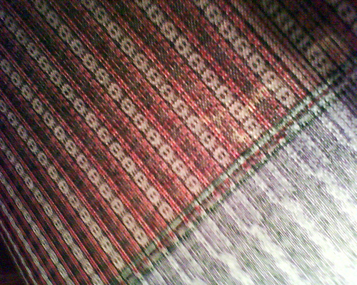
Skull fabric
machining engineering
Image by Cross-stitch ninja
Crappy, crappy mobile telephone pic, but I am so excited about this! It was the very first time we had been permitted to use the huge knitting machines at school!
We did everything, from designing the pattern to setting the machine. This is what I’ve been waiting for given that I decided to start off studying again.

Cool Machining Engineering images

Cool Machining Engineering images

Some cool machining engineering pictures:

Image from web page 485 of “American engineer and railroad journal” (1893)
machining engineering
Image by World wide web Archive Book Photos
Identifier: americanengineer68newy
Title: American engineer and railroad journal
Year: 1893 (1890s)
Authors:
Subjects: Railroad engineering Engineering Railroads Railroad cars
Publisher: New York : M.N. Forney
Contributing Library: Carnegie Library of Pittsburgh
Digitizing Sponsor: Lyrasis Members and Sloan Foundation

View Book Web page: Book Viewer
About This Book: Catalog Entry
View All Photos: All Pictures From Book

Click right here to view book on-line to see this illustration in context in a browseable on the internet version of this book.

Text Appearing Before Image:
qually satisfactory. The tiny enginedrives drills and valve-facing tools straight by implies of theStow flexible shaft. The identical practise also prevails here, ason the other road, in the building of pistons. A hollowpislon with rings sprung in is employed, but the rings are muchnarrower than on the New York, Lake Erie &amp Western. Mr.Foster makes use of a ring only | in. wide, and finds them perfectlysatisfactory. There is a strategy of holding the split rings out 496 THE AMERICAN ENGINEER [November, 1894. right here, nonetheless, that—to us at least—is novel. It is well knownthat if a ring is turned to a bigger diameter than that of thecylinder in which it is to run, when it is sprung in it will beout of round. To obviate this difficulty and, at the same time,hold an outward pressure on the ring, it is turned to match thecylinder. Yet another and slightly heavier ring is turned to adiameter a trifle bigger than the inside of the outer ring, andthe outer ring slipped more than it. Then, wheu they are both com-

Text Appearing Soon after Image:
BALANCED VALVE, FALL BROOK COAL CO. pressed and place in thecylinder, the outer ring is round, whilethe inner keeps it nicely out against the walls. The vehicle shops adjoin the machine shop, and are fitted withthe usual complement of woodworking tools. The floor roomconsists of three tracks, each capable of holding 5 automobiles. AllCars coming in for rebuilding and all new rolling stock areequipped with the Gould coupler and the Westinghouse airbrake. The nicknames bestowed up-on a variety of varieties of locomotivesby the men constructing or runningthem have come to have a trulytechnical significance but it is sel-dom that a nickname is acceptedby the motive energy departmentwith the gravity of a name appliedto one particular of the locomotives on thisroad. All the engines have namesas nicely as numbers, although theformer are a mere ornament andnot used in reports or orders. Acertain locomotive had the misfor-tune to jump from a high trestle atIthaca, and was forthwith dubbedthe Sam Patrh by the males. Re-pairs naturally

Note About Pictures
Please note that these pictures are extracted from scanned page images that might have been digitally enhanced for readability – coloration and appearance of these illustrations may possibly not completely resemble the original work.

Image from page 423 of “Manual for railroad engineers and engineering students : containing the guidelines and tables necessary for the location, building, and equipment of railroads as constructed in the United States” (1883)
machining engineering
Image by Web Archive Book Pictures
Identifier: manualforrailroa00vose
Title: Manual for railroad engineers and engineering students : containing the rules and tables needed for the place, building, and equipment of railroads as constructed in the United States
Year: 1883 (1880s)
Authors: Vose, George L. (George Leonard), 1831-1910
Subjects: Railroad engineering
Publisher: Boston : Lee and Shepard
Contributing Library: Northeastern University, Snell Library
Digitizing Sponsor: Northeastern University, Snell Library

View Book Page: Book Viewer
About This Book: Catalog Entry
View All Images: All Pictures From Book

Click right here to view book on-line to see this illustration in context in a browseable on-line version of this book.

Text Appearing Before Image:
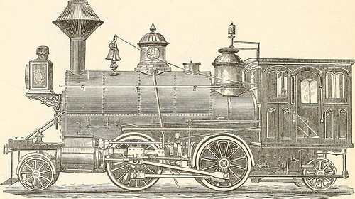
Fig- 157- Fig. 157 and the addition of a related truck behind gives thetank engine, made by Mr. Hudson, of the Rogers Locomotive 398 MANUAL FOR RAILROAD ENGINEERS. Functions, shown in Fig. 158, a most excellent machine for switching,construction, branch, and even light passenger service.*

Text Appearing Soon after Image:
Fig. 158. Iig- 1S9 shows a six-wheeled tank engine, which, upon a toler-ably straight track, is a quite effective machine, but upon sharp

Note About Images
Please note that these images are extracted from scanned web page photos that may possibly have been digitally enhanced for readability – coloration and look of these illustrations may not completely resemble the original work.

Good Machining Engineering images

Good Machining Engineering images

A couple of nice machining engineering images I identified:

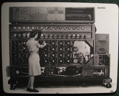
US Navy Cryptanalytic Bombe
machining engineering
Image by brewbooks
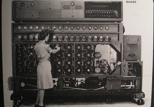
A US Navy WAVE sets the Bombe rotors prior to a run

The US NAvy cryptanalytic Bombes had only one particular purpose: Decide the rotor settings utilized on the German cipher machine ENIGMA. Initially created by Joseph Desch with the National Cash Register Firm in Dayton, Ohio, the Bombes worked mainly against the German Navy’s four-rotor ENIGMAs. Without the correct rotor settings, the messages were practically unbreakable. The Bombes took only twenty minutes to complete a run, testing the 456,976 feasible rotor settings with a single wheel order. Various Bombes attempted various wheel orders, and a single of them would have the final appropriate settings. When the a variety of U-boat settings have been identified, the Bombe could be switched over to operate on German Army and Air Force 3-rotor messages.
Supply: National Cryptologic Museum

Comment on the above
The 4 rotor program had 26^4 or 456,976 settings whilst the theree rotor technique had 26^three or 17,756 settings. It appears like the dilemma scale in a linear way as it took 50 seconds to verify 17,756 setting (~350 per second) whilst the 4 rotor resolution in 20 minutes is ~ 380 settings per second.

I also think the designer Joseph Desch sounds like a remarkable engineer that I never ever heard of just before.

Bombe on Wikipedia
As soon as the British had offered the Americans the information about the bombe and its use, the US had the National Cash Register Company manufacture a great several extra bombes, which the US then utilised to help in the code-breaking. These ran significantly quicker than the British version, so quick that as opposed to the British model, which would freeze quickly (and ring a bell) when a attainable answer was detected, the NCR model, upon detecting a feasible remedy, had to &quotremember&quot that setting and then reverse its rotors to back up to it (meanwhile the bell rang).

Source of following material : National Cryptologic Museum

Diagonal Board is the heart of the Bombe unit. Electrically, it has 26 rows and 26 columns of points, each with a diagonal wire connection. These wires connect every single letter in a column with the exact same position in each and every row. A letter cannot plug into itself these are recognized as &quotself-steckers.&quot The resulting pattern is a series of diagonal lines. The purpose of the diagonal board is to eliminate the complications brought on by the Enigma’s plugboard. Provided particular rotor settings, only specific plugboard settings can result in the proper encrypted letter. The diagonal board disproved hundreds of rotor settings, permitting for only a handful of possibly right settings to outcome in a &quotstrike&quot.

Amplifier Chassis had two purposes, very first to detect a hit and second to decide if it was useful. It supplied the tie-in from the diagonal board, the locator, and the printer circuits.

Thyratron Chassis was the machine’s memory. Considering that the wheels spun at such a high speed, they could not instantly quit rotating when a correct hit was detected. The Thyratron remembered exactly where the appropriate hit was located and indicated when the Bombe has rewound to that position. It also told the machine when it had completed a run and gave the final stop signal.

Switch Banks tell the Bombe what plain to cipher letters to search for. Utilizing menus sent to the Bombe deck by cryptanalysts, WAVES set each dial making use of unique wrenches. 00 equates to the letter A and 25 to the letter Z. The dials work together in groups of two. 1 dial is set to the plain test letter and the other to its corresponding cipher letter as determined by cryptanalysts. There are sixteen sets of switch banks, however, only fourteen had been required to comprehensive a run. As the machine worked through the rotor settings, a correct hit was possible if the electrical path in all fourteen switch banks corresponded to every of their assigned plaintext/cipher combinations.

Wheel Banks represent the 4 rotors used on the German U-boat Enigma. Every column interconnects the 4 rotors, or commutators, in that column. The leading commutator represented the fourth, or slowest, rotor on the Enigma, although the bottom wheel represented the rightmost, or fastest, rotor. The WAVES set the rotors according to the menu developed by the cryptanalysts. The 1st have been set to 00, and each set soon after that corresponded to the plain/cipher hyperlink with the crib (the assumed plain test corresponding to the cipher text.) Normally this meant that each wheel bank stepped up one spot from the 1 on its left. When the machine ran, each bottom rotor stepped forward, and the machine electrically checked to see if the assigned situations had been met. If not, as was generally the case, every bottom wheels moved 1 a lot more place forward. Nonetheless, the bottom commutator moved at 850 rpm, so it only took twenty minutes to full a run of all 456,976 positions.

Printer automatically printed the details of a attainable hit. When the Bombe determined that all the possible conditions had been met. it printed wheel order, rotor settings and plugboard connections.

Motor Manage Chassis controlled both forward and reverse motors. The Bombe was an electromechanical machine and needed a number of gauges for monitoring. It also necessary a Braking Assembly to slow the forward motion when a hit was detected and to bring the machine to a complete quit when a run was completed.

i09_0214 129

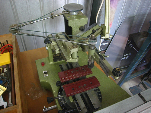
Engraving machine
machining engineering
Image by brotherlywalks

Nice Fast Prototyping In China images

Nice Fast Prototyping In China images

Some cool rapid prototyping in china pictures:

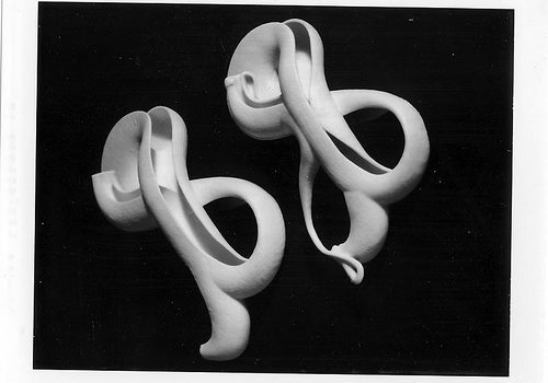
pfc_07_17-copy-1
rapid prototyping in china
Image by core.formula
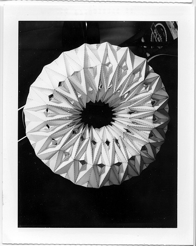
Prefab china

A collection of speedy prototyping models (ZPrint) created in the Pratt Institute College of Architecture 2007 PreFab China Design and style Studio,Evan Douglis, Richard Sarrach, Che-Wei Wang, Eric Wong

Work created by: Sebastian Misiurek, Alex Drabyk, and Ivan Delgado

Please go to www.core.kind-ula.com + www.prefabchina.com for more

All photos are scanned from the proof poloroid of a massive format 4×5 camera. The photographer is Kim Keever and will be component of the upcoming publication Autogenic Structures by Evan Douglis

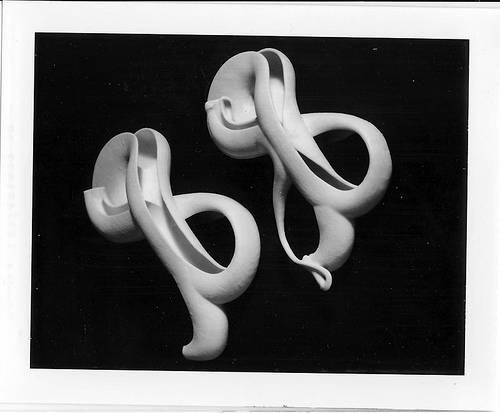
pfc_07_07-copy-1
rapid prototyping in china
Image by core.formula
A collection of rapid prototyping models (ZPrint) designed in the Pratt Institute School of Architecture 2007 PreFab China Style Studio:Evan Douglis, Richard Sarrach, Che-Wei Wang, Eric Wong

Perform by: Chris Egervary , Matt Macher , Ed Mulligan and Jun Pak
Please visit www.core.kind-ula.com + www.prefabchina.com for more

Good Precision Engineering Services images

Good Precision Engineering Services images

Some cool precision engineering solutions pictures:

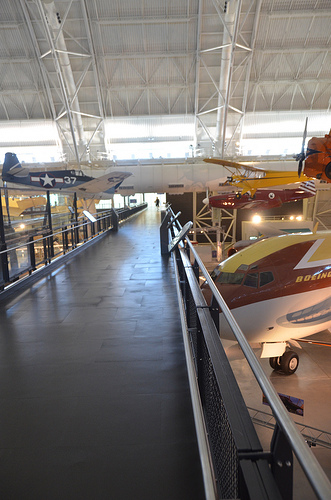
Steven F. Udvar-Hazy Center: south hangar panorama, including Grumman F6F-three Hellcat, North American P-51C “Excalibur III”, Grumman G-22 “Gulfhawk II”, Boeing 367-80 (707) Jet Transport among other folks
precision engineering services
Image by Chris Devers
Quoting Smithsonian National Air and Space Museum | Grumman F6F-three Hellcat:

The Grumman F6F Hellcat was originally conceived as an advanced version of the U.S. Navy’s then current front-line fighter, the F4F Wildcat (see NASM collection). The Wildcat’s intended replacement, the Vought F4U Corsair (see NASM collection), 1st flown in 1940, was showing excellent guarantee, but improvement was slowed by issues, including the crash of the prototype.

The National Air and Space Museum’s F6F-3 Hellcat, BuNo. 41834, was constructed at Grumman’s Bethpage, New York, factory in February 1944 below contract NOA-(S)846. It was delivered to the Navy on February 7, and arrived in San Diego, California, on the 18th. It was assigned to Fighter Squadron 15 (VF-15) on USS Hornet (CV12) bound for Hawaii. On arrival, it was assigned to VF-3 where it sustained harm in a wheels-up landing at NAS Barbers Point, Hawaii. Soon after repair, it was assigned to VF-83 where it was utilized in a training part till February 21, 1945. Following numerous transfers 41834 was converted to an F6F-3K target drone with the installation of sophisticated radio-manage equipment. It was painted red with a pink tail that carried the number 14. Its mission was to be utilised in Operation Crossroads – the atomic bomb tests at Bikini Atoll. It flew on June 24, 1946, with a pilot, on a practice flight and was launched, unmanned, quickly after the 1st bomb test. Instrumentation on board and photographic plates taped to the control stick obtained data on radioactivity. 3 much more manned flights preceded the final unmanned flight on July 25, 1946, which evaluated the very first underwater explosion. Records indicate that exposure of this aircraft to the radioactive cloud was minimal and residual radiation is negligible.

F6F-3K 41834 was transferred to NAS Norfolk and logged its last flight on March 25, 1947, with a total of 430.2 flying hours. It was assigned to the National Air Museum on November three, 1948, and remained at Norfolk until October 4, 1960, when it was moved by barge to Washington and placed in storage. In 1976 this Hellcat was loaned to the USS Yorktown Museum at Charleston, South Carolina. A superficial restoration was performed at the museum, but due to the fact of the harsh atmosphere and its poor condition the Hellcat was returned to NASM on March 16, 1982. In 1983, it was sent to Grumman Aerospace exactly where a group of volunteers totally restored the aircraft. In 1985, it was shipped back to the Paul E. Garber Preservation, Restoration and Storage Facility in Suitland, Maryland, and place in storage. NASM’s F6F-three Hellcat is scheduled to be displayed in the new Steven F. Udvar-Hazy center at Dulles International Airport in Virginia in 2004.

Transferred from the United States Navy.

Manufacturer:
Grumman Aircraft Engineering Corporation

Date:
1943

Country of Origin:
United States of America

Dimensions:
Overall: 338 x 1021cm, 4092kg, 1304cm (11ft 1 1/16in. x 33ft five 15/16in., 9021.2lb., 42ft 9 three/8in.)

Physical Description:
Heavy armor plate, reinforced empennage, R-2800-10W engine, spring tabs on the ailerons (enhanced maneuverability), could carry rockets as properly as bombs.

• • • • •

Quoting Smithsonian National Air and Space Museum | North American P-51C, &quotExcalibur III&quot:

On May 29, 1951, Capt. Charles F. Blair flew Excalibur III from Norway across the North Pole to Alaska in a record-setting 10½ hours. Employing a technique of meticulously plotted &quotsun lines&quot he developed, Blair was in a position to navigate with precision where conventional magnetic compasses often failed. Four months earlier, he had flown Excalibur III from New York to London in significantly less than 8 hours, breaking the existing mark by more than an hour.

Excalibur III 1st belonged to famed aviator A. Paul Mantz, who added extra fuel tanks for lengthy-distance racing to this standard P-51C fighter. With it Mantz won the 1946 and 1947 Bendix air race and set a transcontinental speed record in 1947 when the airplane was named Blaze of Noon. Blair bought it from Mantz in 1949 and renamed it Excalibur III, after the Sikorsky VS-44 flying boat he flew for American Export Airlines.

Present of Pan American Planet Airways

Manufacturer:
North American Aircraft Firm

Date:
1944

Country of Origin:
United States of America

Dimensions:
Wingspan: 11.three m (37 ft)
Length: 9.eight m (32 ft three in)
Height: three.9 m (12 ft 10 in)
Weight, empty: four,445 kg (9,800 lb)
Weight, gross: 5,052 kg (11,800 lb)
Best speed: 700 km/h (435 mph)

Materials:
Overall: Aluminum

Physical Description:
Single seat, single engine, low wing monoplane, Planet War II fighter modified for racing.

• • • • •

Quoting Smithsonian National Air and Space Museum | Grumman G-22 &quotGulfhawk II&quot:

One particular of the most fascinating aerobatic aircraft of the 1930s and ’40s, the Grumman Gulfhawk II was constructed for retired naval aviator and air show pilot Al Williams. As head of the Gulf Oil Company’s aviation division, Williams flew in military and civilian air shows around the country, performing precision aerobatics and dive-bombing maneuvers to market military aviation during the interwar years.

The sturdy civilian biplane, with its strong aluminum monocoque fuselage and Wright Cyclone engine, nearly matched the Grumman F3F standard Navy fighter, which was operational at the time. It took its orange paint scheme from Williams’ Curtiss 1A Gulfhawk, also in the Smithsonian’s collection. Williams personally piloted the Gulfhawk II on its final flight in 1948 to Washington’s National Airport.

Present of Gulf Oil Corporation

Manufacturer:
Grumman Aircraft Engineering Corporation

Date:
1936

Nation of Origin:
United States of America

Dimensions:
Wingspan: 8.7 m (28 ft 7 in)
Length: 7 m (23 ft)
Height: three.1 m (10 ft)
Weight, aerobatic: 1,625 kg (3,583 lb)
Weight, gross: 1,903 kg (4,195 lb)
Prime speed: 467 km/h (290 mph)
Engine: Wright Cyclone R-1820-G1, 1,000 hp

Components:
Fuselage: steel tube with aluminum alloy
Wings: aluminum spars and ribs with fabric cover

Physical Description:
NR1050. Aerobatic biplane flown by Key Alford &quotAl&quot Williams as demonstration aircraft for Gulf Oil Business. Similar to Grumman F3F single-seat fighter aircraft flown by the U.S. Navy. Wright Cyclone R-1820-G1 engine, 1000 hp.

• • • • •

Quoting Smithsonian National Air and Space Museum | Boeing 367-80 Jet Transport:

On July 15, 1954, a graceful, swept-winged aircraft, bedecked in brown and yellow paint and powered by 4 revolutionary new engines initial took to the sky above Seattle. Built by the Boeing Aircraft Company, the 367-80, far better recognized as the Dash 80, would come to revolutionize commercial air transportation when its created version entered service as the well-known Boeing 707, America’s initial jet airliner.

In the early 1950s, Boeing had begun to study the possibility of generating a jet-powered military transport and tanker to complement the new generation of Boeing jet bombers entering service with the U.S. Air Force. When the Air Force showed no interest, Boeing invested million of its personal capital to create a prototype jet transport in a daring gamble that the airlines and the Air Force would buy it after the aircraft had flown and confirmed itself. As Boeing had accomplished with the B-17, it risked the business on one particular roll of the dice and won.

Boeing engineers had initially primarily based the jet transport on studies of improved designs of the Model 367, much better recognized to the public as the C-97 piston-engined transport and aerial tanker. By the time Boeing progressed to the 80th iteration, the design and style bore no resemblance to the C-97 but, for safety reasons, Boeing decided to let the jet project be identified as the 367-80.

Function proceeded rapidly following the formal commence of the project on May 20, 1952. The 367-80 mated a large cabin primarily based on the dimensions of the C-97 with the 35-degree swept-wing design and style based on the wings of the B-47 and B-52 but considerably stiffer and incorporating a pronounced dihedral. The wings were mounted low on the fuselage and incorporated high-speed and low-speed ailerons as nicely as a sophisticated flap and spoiler method. Four Pratt &amp Whitney JT3 turbojet engines, every single creating 10,000 pounds of thrust, had been mounted on struts beneath the wings.

Upon the Dash 80’s 1st flight on July 15, 1954, (the 34th anniversary of the founding of the Boeing Firm) Boeing clearly had a winner. Flying 100 miles per hour quicker than the de Havilland Comet and substantially larger, the new Boeing had a maximum range of much more than three,500 miles. As hoped, the Air Force bought 29 examples of the design and style as a tanker/transport right after they convinced Boeing to widen the style by 12 inches. Satisfied, the Air Force designated it the KC-135A. A total of 732 KC-135s have been constructed.

Speedily Boeing turned its interest to selling the airline business on this new jet transport. Clearly the sector was impressed with the capabilities of the prototype 707 but never far more so than at the Gold Cup hydroplane races held on Lake Washington in Seattle, in August 1955. For the duration of the festivities surrounding this event, Boeing had gathered numerous airline representatives to appreciate the competitors and witness a fly past of the new Dash 80. To the audience’s intense delight and Boeing’s profound shock, test pilot Alvin &quotTex&quot Johnston barrel-rolled the Dash 80 more than the lake in full view of thousands of astonished spectators. Johnston vividly displayed the superior strength and overall performance of this new jet, readily convincing the airline business to get this new airliner.

In searching for a market place, Boeing discovered a prepared buyer in Pan American Airway’s president Juan Trippe. Trippe had been spending considerably of his time browsing for a suitable jet airliner to allow his pioneering business to keep its leadership in international air travel. Functioning with Boeing, Trippe overcame Boeing’s resistance to widening the Dash-80 style, now identified as the 707, to seat six passengers in every single seat row rather than five. Trippe did so by placing an order with Boeing for 20 707s but also ordering 25 of Douglas’s competing DC-8, which had yet to fly but could accommodate six-abreast seating. At Pan Am’s insistence, the 707 was created 4 inches wider than the Dash 80 so that it could carry 160 passengers six-abreast. The wider fuselage created for the 707 became the regular design and style for all of Boeing’s subsequent narrow-body airliners.

Even though the British de Havilland D.H. 106 Comet and the Soviet Tupolev Tu-104 entered service earlier, the Boeing 707 and Douglas DC-eight had been larger, faster, had greater variety, and had been much more profitable to fly. In October 1958 Pan American ushered the jet age into the United States when it opened international service with the Boeing 707 in October 1958. National Airlines inaugurated domestic jet service two months later using a 707-120 borrowed from Pan Am. American Airlines flew the 1st domestic 707 jet service with its own aircraft in January 1959. American set a new speed mark when it opened the 1st frequently-scheduled transcontinental jet service in 1959. Subsequent nonstop flights between New York and San Francisco took only 5 hours – 3 hours significantly less than by the piston-engine DC-7. The one-way fare, such as a surcharge for jet service, was 5.50, or 1 round trip. The flight was nearly 40 % faster and virtually 25 % cheaper than flying by piston-engine airliners. The consequent surge of traffic demand was substantial.

The 707 was initially created for transcontinental or a single-stop transatlantic range. But modified with added fuel tanks and far more effective turbofan engines, the 707-300 Intercontinental series aircraft could fly nonstop across the Atlantic with full payload beneath any conditions. Boeing constructed 855 707s, of which 725 had been purchased by airlines worldwide.

Obtaining launched the Boeing Organization into the industrial jet age, the Dash 80 soldiered on as a very effective experimental aircraft. Till its retirement in 1972, the Dash 80 tested numerous sophisticated systems, a lot of of which had been incorporated into later generations of jet transports. At one particular point, the Dash 80 carried 3 different engine sorts in its four nacelles. Serving as a test bed for the new 727, the Dash 80 was briefly equipped with a fifth engine mounted on the rear fuselage. Engineers also modified the wing in planform and contour to study the effects of distinct airfoil shapes. Many flap configurations were also fitted including a highly sophisticated method of &quotblown&quot flaps which redirected engine exhaust over the flaps to improve lift at low speeds. Fin height and horizontal stabilizer width was later elevated and at one point, a specific several wheel low pressure landing gear was fitted to test the feasibility of operating future heavy military transports from unprepared landing fields.

After a long and distinguished profession, the Boeing 367-80 was ultimately retired and donated to the Smithsonian in 1972. At present, the aircraft is installated at the National Air and Space Museum’s new facility at Washington Dulles International Airport.

Gift of the Boeing Organization

Manufacturer:
Boeing Aircraft Co.

Date:
1954

Nation of Origin:
United States of America

Dimensions:
Height 19′ 2&quot: Length 73′ 10&quot: Wing Span 129′ eight&quot: Weight 33,279 lbs.

Physical Description:
Prototype Boeing 707 yellow and brown.

Cool Metal Components China images

Cool Metal Components China images

Verify out these metal parts china pictures:

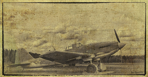
The Soviet WWII Ground-Attack Aircraft Ilyushin Il-10 ‘Shturmovik’. Poland. 1945. Советский штурмовик Ил-10. Польша 1945 г.
metal parts china
Image by Peer.Gynt
DIGITALLY COMPOSED IMAGE
The original aircraft is exposed in Central AirForce Museim, Monino.

Ilyushin Il-10 (Cyrillic Илью́шин Ил-ten, NATO reporting name: &quotBeast&quot) was a Soviet ground attack aircraft developed at the finish of Globe War II by the Ilyushin construction bureau. It was also license-built in Czechoslovakia by Avia as the Avia B-33.
Improvement

From the start of Eastern Front combat in Globe War II, the Soviet Air Force (VVS) utilized the effective ground attack aircraft Ilyushin Il-two Sturmovik, powered by the Mikulin AM-38 inline engine. As the war progressed, the Soviets laid plans for that aircraft’s successor. The principal objective was to increase speed and maneuverability at low altitudes, primarily to evade tiny-caliber anti-aircraft artillery, which was the major threat for ground attack aircraft, and to eliminate some of the Il-2’s faults. The most promising project was a modern day, light and maneuverable close assault aircraft, the Sukhoi Su-six, developed by Pavel Sukhoi’s bureau from 1942. At the same time, Sergei Ilyushin developed a heavier aircraft, the VSh or Il-8 M-71, derived from the Il-two style, and on which it was partly based. Each projects were powered by the prototype M-71 radial engine, which did not enter production.

In 1943, Ilyushin began perform on a new aircraft, Il-1, which was to be a 1- or 2-seat heavily armoured fighter-interceptor, meant mainly for fighting enemy bombers and transports. The Il-1 was related to the Il-two design, but was much more contemporary, compact, and powered with a new Mikulin engine: the AM-42. But the VVS gave up the concept of heavy armoured fighters, due to their low speed, which was not enough to intercept contemporary bombers. As a result, Ilyushin decided to turn the Il-1 into a two-seat ground attack plane, with the designation changed to Il-10 in early 1944 (odd numbers had been reserved for fighters).

At that time, Ilyushin also finished a prototype of a heavier ground attack plane, the Il-eight, using the same engine, and a lot more closely derived from the Il-2. It carried a higher payload (1,000 kg/2,204 lb), but had decrease functionality than the Il-ten. Both sorts first flew in April 1944, the Il-10 proving significantly superior to the Il-8, which had poor handling. The Il-10 successfully passed trials in early June 1944.

The third competitor was a new variant of the Sukhoi Su-six, also powered by the AM-42 engine. After comparative tests, the Il-ten was deemed the winner and was chosen as the new ground attack plane, despite some opinions that the Su-6 was a better aircraft, notwithstanding inferior functionality and payload, with better gun armament. Notably, the Su-six prototype was tested with maximum payload, causing lowered efficiency, whilst the Il-ten was tested with regular payload. Some benefits of the Il-10 came from its technical similarity to the Il-2.
On 23 August 1944 the Il-10 was ordered into serial production by selection of the State Defense Committee (GKO) as a new ground attack plane.[five] Its armament was initially equivalent to late model Il-2s, with two 23 mm VYa-23 cannons and two ShKAS machine guns in the wings, and a 12.7 mm UBT machine gun for a rear gunner, and 400 kg, or a maximum 600 kg of bombs. As opposed to the Il-2 and Su-six, it was not initially meant to carry rockets.

Production of the Il-10 started in Kuybyshev’s factories No. 1 and No. 18. The very first production aircraft flew on 27 September 1944 and 99 aircraft have been produced by the finish of 1944. Early series aircraft showed teething troubles, most notably engine faults and fires. Most problems have been eliminated by 1945. Aircraft produced from April 1945 onwards could carry 4 unguided air-to ground rockets. Aircraft developed from 1947 onwards have been fitted with stronger armament, consisting of 4 23 mm NS-23 cannons in the wings and a 20 mm cannon for the rear gunner. Il-10 production ended in 1949, after a run of four,600 aircraft in the final two years, they were made in factory No. 64.

Between 1945 and 1947, 280 UIl-two or Il-10U trainer variants have been produced. The rear gunner’ cockpit was replaced with a longer instructor’s cockpit with dual controls. Its functionality and building had been equivalent to the combat variant apart from armament, which was lowered to two cannons, two rockets, and a standard load of bombs.

In 1951, the Czechoslovak firm Avia secured a license to make Il-10s, with the designation B-33. The very first one particular flew on 26 December 1951. Initially, their engines had been Soviet-constructed. From 1952 onwards the engines were also made in Czechoslovakia as the M-42. Besides the combat variant, a Czechoslovak trainer variant also entered service below the designation CB-33. In total, 1,200 B-33s had been constructed by 1956.
In 1951, due to encounter acquired throughout the Korean War, the Soviet Air Force decided that propeller ground attack aircraft may possibly still be valuable, and decided to renew Il-ten production in a modified variant, the Il-10M, which 1st flew on 2 July 1951. It was a bit longer, with a wider wingspan, and bigger handle surfaces, with a fin below the tail. Four of the more lately developed NR-23 cannons had been mounted in the wings, while the payload stayed the same, and newer navigation gear was installed, giving partial all-climate capability. Speed decreased slightly, but handling enhanced. Between 1953 and 1954, 146 Il-10Ms were produced, all but ten in Rostov-on-Don’s factory No.168.

In total, six,166 of all Il-10 variants were made, which includes those built beneath license.

Trials of Il-10s mounted with a lot more potent AM-43 and AM-45 engines took spot, but proved unsuccessful. Ilyushin next created a lighter close help aircraft, the Il-16, with improved performance and similar armament. It initial flew on ten June 1945. A short run entered production, but the project was cancelled in 1946 due to the AM-43 engine’s unreliability.
Technical description

The airframe featured a single engine, two-seat, monoplane, with a metal-covered frame. The plane was hugely armoured. The front portion of the fuselage, with the cockpit, was a shell of armour plates 4–8 mm thick the thickest, 8 mm, were below the engine, there was no armour above the engine. The front windshield was produced of armour glass 64 mm (two.five in) thick. Also armoured was: a roof above the pilot, side window frames in the pilot’s cab, a wall amongst crew seats, and a rear wall behind the cab. Total armour weight was 994 kg, which includes its attachment. The wing consisted of a central section, with two bomb bays, and two detachable outer panels. The undercarriage was retractable. The main wheels folded to the rear right after rotating by 86°.

Early Il-10s had two 23 mm VYa-23 autocannons (150 rounds each and every) and two 7.62 mm ShKAS machine guns (750 rounds every) fixed in wings, and a 12.7 mm UBT machine gun in a rear gunner station BU-eight, with 150 rounds. The horizontal angle of the rear machine gun field of fire was 100°. From 1947, the aircraft have been armed with 4 NS-23 23 mm cannons in the wings (150 rounds each and every) and 20 mm B-20T cannon in a rear gunner station BU-9 (150 rounds). The IL-10M had four 23 mm NR-23 cannons in wings (150 rounds every) and 20 mm B-20EN cannon in a rear gunner station BU-9M (150 rounds). Avia B-33 had four 23 mm NS-23RM cannons in wings and 20 mm B-20ET cannon in a rear gunner station BU-9M.

The typical bomb load was 400 kg, maximum load was 600 kg. This could be tiny fragmentation or anti-tank bomblets, place in bomb bays, or four 50–100 kg bombs in bomb bays and externally below wings, or two 200–250 kg bombs attached under wings. Modest bomblets have been place directly on bomb bay floors, in piles. A standard load was 182 (maximum 200) 2 kg AO-two,5-two fragmentation bombs, or 144 PTAB-2,five-1,five anti-tnk HEAT bombs. Apart from bombs, 4 unguided rockets RS-82 or RS-132 could be carried on rail launchers beneath wings. Avia B-33s were also fitted to carry other rocket kinds. Late Soviet aircraft could carry ORO-82 and ORO-132 tube launchers. In the tail section was a DAG-10 launcher with ten anti-aircraft or anti-personnel grenades AG-two (soon after getting thrown, they would fall with parachutes and then burst, but had been not extensively used in practice).

The Il-ten engine was a 12-cylinder inline V engine Mikulin AM-42, liquid-cooled, power: 1,770 hp continuous, takeoff energy: two,000 hp. Three-blade propeller AV-5L-24 of three.six m diameter. Two fuel tanks in the fuselage: upper 440 l more than engine, ahead of the cockpit, and decrease tank of 290 l under the cockpit. The aircraft had a radio set and a camera AFA-1M in a rear section of the fuselage.
Operational history

In October 1944, the Il-10 initial entered service with coaching units in the Soviet Air Force. In January 1945, the first Il-10 combat unit entered service with the 78th Guards Assault Aviation Regiment, but it did not enter action due to unfinished training. Nonetheless, 3 other Il-ten units managed to take element in the final combat actions of World War II in Europe. They were the 571st Assault Aviation Regiment (from 15 April 1945), the 108th Guards Assault Aviation Regiment (from 16 April 1945), and the 118th Guards Assault Aviation Regiment (on 8 May 1945). About a dozen aircraft have been destroyed by flak or engine breakdowns, but the Il-ten appeared to be a profitable style. One particular was shot down by an Fw 190 fighter, but a crew of the 118th Regiment shot down one more Fw 190 and probably damaged one more. On ten Could 1945, the day soon after the official Soviet finish of the war, (Victory Day), there had been 120 serviceable Il-10s in Soviet Air Force combat units, and 26 disabled ones.

Right after the USSR reentered the war against the Empire of Japan, with the invasion of Manchuria, from 9 August 1945, one particular Il-ten unit, the 26th Assault Aviation Regiment of the Pacific Navy Aviation, was utilised in combat in the Korean Peninsula, attacking Japanese ships in Rasin and rail transports.

Right after the war, until the early 1950s, the Il-10 was a basic Soviet ground attack aircraft. It was withdrawn from service in 1956. At the very same time, operate on new jet-powered devoted armoured ground attack planes (like the Il-40) was canceled, and the Soviets turned to multipurpose fighter-bomber aviation. The Il-10 and its licensed variant, the Avia B-33, became a standard ground attack plane of the Warsaw Pact nations. From 1949 to 1959, the Polish Air Force utilised 120 Il-10s (including 24 UIl-ten), and 281 B-33s. In Poland, the B-33 was modified to carry 400 l fuel tanks below its wings. From 1950 to 1960, Czechoslovakia utilized 86 Il-10s, including six UIl-10s, and about 600 B-33s. From 1949 to 1956, the Hungarian Air Force utilised 159 Il-10s and B-33s. From 1950 to 1960, the Romanian Air Force utilised 14 Il-10s and 156 B-33s. Bulgaria also utilized these aircraft.

In the late 1940s, 93 Il-10 and UIl-10s had been offered to North Korea. They had been then used in the 57th Assault Aviation Regiment throughout the early phase of the Korean War. They have been initially utilised with achievement against the weak anti-aircraft defense of South Korean forces, but then they suffered heavy losses in encounters against the USAAF fighters and have been bombed on the ground themselves. Right after numerous weeks, about 20 remained. In the summer season of 1950, North Korea received more aircraft from the USSR. The North Koreans claimed to sink a warship on 22 August 1950 with Il-10s, but it was in no way confirmed.

From 1950, Il-10s have been employed by the People’s Republic of China, in two regiments of an assault aviation division. They had been employed in combat in the course of a conflict with the Republic of China, (Taiwan), over border islands in January 1955. They remained in service till 1972. From 1957, Yemen employed 24 B-33s.

General traits
Crew: two, pilot and gunner
Length: 11.12 m (36 ft six in)
Wingspan: 13.40 m (44 ft)
Height: four.10 m (13 ft five in)
Wing area: 30 m2 (322.9)
Empty weight: 4,675 kg (10,305 lb)
Loaded weight: 6,345 kg (14,000 lb)
Max. takeoff weight: six,537 kg (14,410)
Powerplant: 1 × Mikulin AM-42 liquid-cooled V-12, 1,320 Kw (1,770 hp)

Performance
Maximum speed: 550 km/h at 2,700 m 500 km/h at ground level (340 mph at 8,860 ft / 310 mph)
Range: 800 km (500 mi)
Service ceiling: 4,000 m (13,123 ft)
Wing loading: 211 kg/m2 (43.two lb/ft2)

Armament

two × 23 mm Nudelman-Suranov NS-23 auto cannons in wings, 150 rounds per gun
two × 7.62 mm ShKAS machine guns in wings, 750 rounds per gun
1 × 12.7 mm UBST machine gun in the BU-9 rear gunner station, 190 rounds
Up to 600 kg (1,320 lb) of numerous weapons as described in the text.

Wikipedia