Nice Precision Engineering Companies photographs

Nice Precision Engineering Companies photographs

A few nice precision engineering companies images I found:

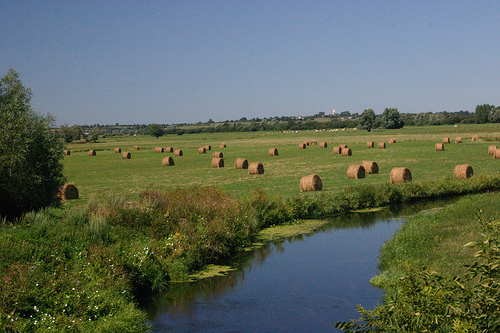
Band of Brothers: The La Fiere Bridge over the Merderet River
precision engineering companies
Image by Dog Company
This isn’t an Easy Company 506th site, but this set is dedicated to all of the paratroopers, and I think you’ll be interested in this.

In this picture, I’m standing on the La Fiere Bridge over the Merderet River, about 1-2 km west of Ste Mere Eglise. On D-Day, this field was flooded. The Germans had jammed the lock on a dam to flood a lot of fields that were potential airborne landing site.

One thing I learned about the consequence is visible in this picture. If you were a paratrooper and you landed in that field, you were in about three feet of water. If you landed in the river, you were in over your head. I read the account of one trooper who landed in the river and had to use his Mae West life preserver to surface. Then as he gasped for air, he had to cut himself out of his harness with his knife, then was able to drag himself to safety. Another account I read was about a trooper who landed in this field, and wind gusts blew him, face down (so he was drowning) across the field until he was able to turn over and get out of his chute.

The Germans were massed to the left of the river, and a small contingent of men from the 82nd Airborne and the 505th of the 101st formed a defense on the right side. They were there for one job: prevent the Germans from counterattacking with armor across the Merderet and hitting the paratroops from their left flank (Ste Mere Eglise would have been totally exposed if they didn’t hold this bridge. At first, they had rifles, carbines and a light mortar, and then they got more equipment. Here are some downloads I clipped from the internet to illustrate

La Fiere Bridge: D-Day June 6, 1944
Around 1:00 a.m. on June 6, 1944, Marcus Heim jumped out of a C-47 transport plane over Normandy, France. Heim was part of A Company, 505, their specific objective was to seize and hold the La Fiere Bridge over the Merderet River until reinforcements from the amphibious portion of the Allied invasion arrived.
"In all of the airborne operations of the ETO, the Merderet Bridgehead was the one attended by the greatest difficulty and hardships of the individual assemblies … these conditions so frequently brought forth the finest characteristics of the American soldier." – S L A Marshall

Enclosed are Marcus Heim’s recollections of June 6. That day, their small four-man team set up a roadblock next to the La Fiere Bridge and was responsible for repelling several powerful German counter attacks.

I landed about twenty-five feet from a road and before I could get my rifle assembled, I heard a motorcycle approaching. I remained still as I did not have time to assemble my rifle, and watched two German soldiers pass by. After they passed and I had my rifle together I found other paratroopers and our equipment bundle and set off for the bridge over the Merderet River. We were to hold the bridge until the soldiers who landed on the beach arrived later that day, but it was three days before they reached our position.
As you stand at the La Fiere Bridge looking in the direction of Ste Mere- Eglise, the Manor House is on the right and was the living quarters. There were several buildings, one a large barn, which was close to the Merderet River. The Germans had occupied the Manor House and were driven out by "A" Company, 505, after heavy fighting. As you pass the Manor House toward Ste Mere-Eglise, the road goes up hill and curves to the left. Across from the Manor House there was a pathway which was about four feet wide and now is a causeway was narrow and had brush and trees on each side, some hung over the causeway. The fields were completely flooded right up to the causeway. The town on Cauquigny was about 800 to 900 yards from the bridge, and it was in German hands. The causeway curved to the right about 60 or 65 yards from the bridge.

Map of The La Fiere Bridge Head. Heim’s position is near the bottomof the map (U.S. Army).
When we arrived at the bridge, men were placed down the pathway to the right and to the left of the Manor House and out buildings. The four bazooka men included: Lenold Peterson, and myself, John Bolderson and Gordon Pryne. Peterson and I took up positions on the Manor House side facing Cauquigny, below the driveway. There was a concrete telephone pole just in front of us and we dug in behind it. We knew that when the Germans started the attack with their tanks, we would have to get out of our foxhole and reveal our position to get a better view of the tanks. Bolderson and Pryne were on the right side of the road just below the pathway. I do not remember how many paratroopers were around us, all I saw was a machine gun set up in the Manor House yard. On the right side down the pathway a few riflemen took up positions.

There was a 57-millimeter cannon up the road in back of us along with another machine gun. We carried antitank mines and bazooka rockets from the landing area. These mines were placed across the causeway about 50 or 60 feet on the other side of the bridge. There was a broken down German truck by the Manor House, which we pushed and dragged across the bridge and placed it across the causeway. All that afternoon the Germans kept shelling our position, and the rumor was that the Germans were going to counter attack. Around 5:00 in the afternoon the Germans started the attack. Two tanks with infantry on each side and in the rear following them was a third tank with more infantry following it. As the lead tank started around the curve in the road the tank commander stood up in the turret to take a look and from our left the machine gun let loose a burst and killed the commander. At the same time the bazookas, 57 millimeter and everything else we had were firing at the Germans and they in turn were shooting at us with cannons, mortars, machine guns and rifle fire. Lenold Peterson and I (the loader), in the forward position got out of the foxhole and stood behind the telephone pole so we could get a better shot at the tanks. We had to hold our fire until the last minute because some of the tree branches along the causeway were blocking our view. The first tank was hit and started to turn sideways and at the same time was swinging the turret around and firing at us. We had just moved forward around the cement telephone pole when a German shell hit it and we hat to jump out of the way to avoid being hit as it was falling. I was hoping that Bolderson and Pryne were also firing at the tanks for with all that was happening in front of us there was not time to look around to see what others were doing. We kept firing at the first tank until it was put out of action and on fire. The second tank came up and pushed the first tank out of the way. We moved forward toward the second tank and fired at it as fast as I could load the rockets in the bazooka. We kept firing at the second tank and we hit it in the turret where it is connected to the body, also in the track and with another hit it also went up in flames. Peterson and I were almost out of rockets, and the third tank was still moving. Peterson asked me to go back across the road and see if Bolderson had any extra rockets. I ran across the road and with all the crossfire I still find it hard to believe I made it to the other side in one piece. When I got to the other side I found one dead soldier and Bolderson and Pryne were gone. Their bazooka was lying on the ground and it was damaged by what I thought were bullet holes. Not finding Bolderson or Pryne I presumed that either one or both were injured. I found the rockets they left and then had to return across the road to where I left Peterson. The Germans were still firing at us and I was lucky again, I return without being hit. Peterson and I put the new found rockets to use on the third tank. After that one was put out of action the Germans pulled back to Cauquigy and continued shelling us for the rest of the night. They also tried two other counter attacks on our position, which also failed.

During the battles, one does not have time to look around to see how others are doing. We were told that when we took up our position by the bridge that we have to hold it at all cost until the men from the beach arrived, for if the Germans broke through they would have a good chance of going all the way to the beach. Our job was to be in the forward position by the La Fiere Bridge with our bazooka to stop any German tanks from advancing over the bridge and onto Ste Mere-Eglise and the beaches. This we accomplished all the while the Germans were continuously firing everything they had at us. After I went across the road and found more rockets for the bazooka and returned, the third tank was put out of action and the Germans retreated. When the Germans pulled back, we looked around did not see anyone, we than moved back to our foxhole. Looking back up the road toward Ste Mere-Eglise, we saw that the 57-millimeter cannon and the machine gun were destroyed. Looking down the pathway across from the Manor House we could not see any of our men. We were thinking that we were all alone and that maybe we should move from here, then someone came and told us to hold our position and he would find more men to place around us for the Germans may try again to breach our lines. We found out later, of the few that were holding the bridge at this time, most were either killed or wounded. Why we were not injured or killed only the good Lord knows.

Marcus Heim recieves the DSC from General Omar Bradley.
For holding their position and repelling the Germans on June 6, 1944, Heim, Peterson, Bolderson and Pryne were each awarded the Distinguished Service Cross.

The following letter is from John "Red Dog" Dolan, Company Commander of A Company 505 PIR, to General James Gavin. Wriiten in 1959, at the urging of Robert Murphy, the letter provides a very detailed account of A Company’s legendary actions at La Fiere Bridge. General Gavin’s transmittal letter to famed author Cornelius Ryan is also enclosed.
JOHN J. DOLAN
ATTORNEY AT LAW
BOX 1272, 141 MILK STREET
BOSTON 4, MASS.

March 15, 1959

Lt. General James N. Gavin
c/o Arthur D. Little, Inc.
30 Memorial Drive
Cambridge, Mass.

Dear General Gavin:

Thank you for your letter of March 10, 1959. It had always been my intention of answering the questionnaire of Cornelius Ryan; but realizing that it would take considerable time to give a detailed and accurate account, I kept putting it aside and then completely forgot about it until Bob Murphy spoke to me about it a few days before receipt of your letter.

I shall try to cover as much detail without making this letter too voluminous, leaving it to your judgment and discretion to delete any portion that you deem unfavorable to the outfit. You may recall that I was in command of Company "A", 505 Parachute Infantry, with the rank of First Lieutenant. The specific mission of the Company "A" was to seize and defend the bridge crossing the Merderet River on the road that ran East to West from Ste. Mere Eglise, with the purpose of preventing the movement of German troops down to the beach-head.

I don’t recall exactly what time the first Battalion jumped but it was between 1:00 and 2:00 a.m. on D-Day. We hit our drop zone right on the nose, because within twenty minutes to one-half hour, I knew our exact location. I was able to identify a "T" intersection, dirt roads 8 to 10 feet wide, near our drop zone. The upper arm of which ran generally east to west, the vertical arm running north to south, to meet the road running from Ste. Mere Eglise to our objective, the bridge at the Merderet River.

We had the usual problems of re-organization in the dark; however, about an hour before dawn, Company "A" moved out from the drop zone with about ninety (90) per cent of the men accounted for. (This was not due to luck alone, but to the cooperation of Officers, Non-Coms, and last but not least, training. Men who have to fight in the night should be trained in nighttime fighting, not just taken on a night march and digging foxholes.) We moved along this dirt road which I previously referred to as being the North-South arm of the "T" intersection, and just around here, I ran into Major McGinity. He moved out with us.

The order of march was first, Co. Headquarters, third and second platoons in that order. When we reached the road running East-West from Ste. Mere Eglise, a German motorcycle passed us going toward Ste. Mere Eglise. At this time, it was still dark, but daylight was starting to break. We crossed the road and started west toward the bridge,with a hedge row to our right between us and the road. Just about this time, contact was lost with the first platoon, so the third platoon took the lead.

About seven to eight hundred yards from the bridge, we came upon a dirt road running southeasterly from the road to the bridge. Hedgerows were on either side of this road; and beyond it in the direction of the bridge, was an open, flat field, about 100 yards deep and about 75 yards wide. It was here that I figured the Germans would defend if they intended a defense of the bridge.

I directed Lt. Donald Coxon to send his scouts out. This he did, and he also went out with them. He had plenty of personal courage but he didn’t have the heart to order them out without going with them.

A few moments later, a German machine gun opened up, killing Lt. Coxon and one of his scouts, Fergueson. Their fire was returned; and, with Major McGinity and myself leading, a few men holding and returning frontal fire, the platoon flanked to the left. At the same time, I directed Lt. Presnell to re-cross the road and attack along the northern side down to the bridge. This was done, and the second platoon didn’t meet with any fire until they arrived at the bridge.

The third platoon continued its flanking move and cut back in toward the road to the bridge. Because of the fire, we calculated that there was just one machine gun crew that was in our way. It later turned out that there must have been at least a squad dug in at this point, with at least two of them armed with machine pistols. Prisoners captured later, in addition to the German dead, amounted to about the size of one of our platoons. There were no German officers captured. I don’t know whether or not any of their enlisted men escaped.

To continue, we cut back toward the road, travelling in a Northerly direction. Major McGinity was leading and I was about three’ or four paces behind, and slightly to the right. There was a high, thick hedgerow to our left, and it was in here that I figured the machine gun was located.

When we had traveled about two-thirds of the way up the hedgerow, they opened up on us with rifle, and at least two machine pistols. I returned the fire with my Thompson Sub-Machine Gun at a point where I could see leaves in the hedgerow fluttering. Major McGinity was killed instantly. As luck would have it, there was a German foxhole to my left which I jumped into and from where I continued to fire I could only guess where to shoot, but I had to as part of the Third platoon was exposed to their fire. Lt. McLaughlin, the assistant platoon leader was wounded and died later that day. His radio operator was also killed the platoon by now was under fire from two directions, from the point where I was pinned down, and also from the direction of the bridge.

I can’t estimate how long we were pinned down in this fashion, but it was at least an hour. I made several attempts to move, but drew their fire. On my last attempt, I drew no fire. They obviously had pulled out. During all of this time, I could hear rifle and machine gunfire down by the bridge on the north side. This ceased about this time I returned to the rest of the third platoon, instructed the Non-Coms to re-organize and to maintain their present position. I then crossed the road and located the first platoon commanded by Lt. Oakley on the north side. They were moving toward the bridge, so I instructed them to continue and dig in on the right side. I went down to the bridge and found that we had received an assist from some of the 508 Prcht. Infantry about this time, I ran into Col. Eckman, and sent for my third platoon to dig in on the left or south side of the bridge. The first was already digging in on the north side.

I thought that all of the Germans had retreated; but unknown to us, there were about ten or twelve Germans holed up on the second floor of a stucco-type farmhouse. At the time they started firing. Col. Eckman and I were casually looking the situation over. It lasted about twenty minutes with about ten or twelve Germans surrendering. About a squad of men from the 508 made the actual capture.

We dug in, the disposition of my Company as follows: First platoon on the north side of the road, the third on the south and the second in reserve, about 4OO yards back, so that it could also protect the rear.

Major Kellam arrived at the bridge with Capt. Roysden, his S-3. He had most of his C.P. unit with him. I don’t know whether or not a Battalion C.P. had ever been set up as planned, at least, I don’t recall having had any communication with it. Down at the bridge now was most of Company "A", about one platoon or Company "B", a platoon of the Division Engineers (mission to blow the bridge if necessary), about half of Battalion Headquarters Company with mortars awl machine gun sections and several stray men from other regiments. The Company dug in well and quickly. I had just completed my inspection of the forward positions when we knew that an attack was coming. You will recall that in front of our position, west of the Merderet River, was a marsh at least 1000 yards wide at its narrowest point. The road running west from the bridge could better be described as a causeway.

As I recall, the mission of the 508 was to occupy a position beyond this causeway. In addition to the men who assisted us in capturing the bridge at least a company of the 508 passed through our position and moved over the causeway to their objective. They were gone at least an hour when we saw several of them retreating back across the marsh. I remember that we helped several of them out of the river, which was quite shallow.

The machine gun fire from the Germans was very heavy by now. We didn’t return their fire as there were no visible targets and our ammunition supply was limited. They attacked with three tanks, which I was unable to identify for sure; but they appeared to be similar to the German Mark IV type, or maybe a little lighter. The tanks were firing on us with machine guns and cannon.

Just about a half-hour before this attack, a 57MM A. T. gun was assigned to Company "A". I located this gun about 150 yards from the bridge on the road where it curves to the right as you approach the bridge. Incidentally, this was my C.P. and later the Battalion C.P. This gave the gun excellent cover and a good field of fire.

On the bridge I had three bazooka teams. Two of them were from Company "A" and the third was either from "B" or "C" Company. The two Company "A" bazookas were dug in to the left and right of the bridge. Because of the fact that the road itself was the causeway type, they were as of necessity dug in below the level of the road, so that in order to fire, they had to get out of their foxholes. The third bazooka was over more to the south where better cover was available.

To continue, I had just completed my inspection of our defenses and was 40 to 50 yards from the bridge. Major Kellam and Captain Royaden were nearby. The first two tanks were within 15 Qr 20 yards of each other, the third was back about 50 yards. When the lead tank was about 40 or 50 yards away from the bridge, the two Company "A" bazooka teams got up just like clock work to the edge of the road. They were under the heaviest small arms fire from the other side of the causeway, and from the cannon and machine gun fire from the tanks. To this day, I’ll never be able to explain why all four of them were not killed. They fired and reloaded with the precision of well-oiled machinery. Watching them made it hard to believe that this was nothing but a routine drill. I don’t think that either crew wasted a shot. The first tank received several direct hits. The treads were knocked off, and within a matter of minutes it was on fire. Then they went to work on the second tank, and within about 30 seconds, it was on fire. They fired every rocket that they had and then jumped into their foxholes. The 57mm during this time was firing and eventually knocked out the last tank. The gun crew did an excellent job.

My two bazooka crews called for more ammunition. Major Kellam ran up toward the bridge with a bag of rockets followed by Captain Roysden. When they were within 15 or 20 yards of the bridge, the Germans opened up with mortar fire on the bridge. Major Kellam was killed and Captain Roysden was rendered unconscious from the concussion. He died later that day. Both of the bazookas were destroyed by the mortar fire. Lt. Weir (Reg. Hq. Co.) and I carried Captain Roysden back. I then took over command of the battalion, being the senior officer present.

Company "B" was put into reserve in the perimeter of Company "A", so that we had almost a 560 degree perimeter defense. The rest of the day we were under heavy mortar and machine gun fire. The mortar fire was very effective as against the two forward platoons because of tree bursts. It took very little imagination on the part of the Krauts to figure out just where we would be dug in. As I recall, there was less than a seventy-five yard frontage on either side of the bridge from where we could effectively defend, so they could throw their mortar fin in our general direction with good results. During the night, the fire let up, but they started early the next morning and kept it up. My third platoon took the worst beating, as they were in a heavier wooded area, (tree bursts).

The second tank attack came on the afternoon of the second day. I was over on the north side of the bridge with the first platoon. For about an hour before the attack, they increased their mortar fire to the extent that the third platoon was just about knocked out, but not quite. I was not aware of this at the time. In addition to already heavy casualties, Sgt. Monahan, the platoon Sgt. was fatally wounded.

I learned second hand that some other troops had retreated through the third platoon’s position, and then through my C.P. Rumors were around that we were going to give up the bridge. As a result of this, the 57MM A.T. crew took off. I didn’t have an Executive Officer at the time. Earlier that day, he (Tom Furey) was put in command of "C" Company. My First Sergeant was a jump casualty, so my Company Headquarters at the time was non-existent except for runners and radio operators. I can’t recall why, but our radios were not working. The only way that we could communicate was through runners.

The first platoon was under heavy fire also. The platoon leader, Lt. Oakley, who had been doing an excellent job, was fatally wounded, and Sgt. Ricci was leaving the junior squad leader, Sgt. Owens, in command. You will recall that we have had some communication about Sgt. Owens in the past as to his personal courage and the way he commanded the platoon at this most critical time. I recommended Sgt. Owens and my tour bazooka men for the D.S.C. The bazooka men were awarded the D.S.C., but Sgt. Owens was not. This is a story in itself.

The second attack was with two tanks and infantry. I was unable to estimate the size. The tanks stayed out of effective bazooka range. (We had one bazooka left.) Not hearing any fire from the 57MM, I went over to it and found it unmanned. I tried to fire it, but the crew had taken the firing mechanism. I organized five or six men behind the hedge on the southerly side of the road with Gammon grenades, and just about this time, two of the gun crew returned with the firing mechanism. They knocked out the two tanks. They were two youngsters not more than 17 or 18 years old, who returned on their own initiative. I recommended them for Silver Stars.

The rest of our stay at the bridge was uneventful, except for the continued mortar fire, and at the end, artillery fire which damaged the 57MM. Lt. Col. Mark Alexander took over command of the battalion later that day and continued to command it for most of the operation. Without exception, he was the finest battalion commander I ever served under. My second son, Mark Alexander Dolan, was named after him.

In conclusion, we held the bridge until relieved. In Co. "A" alone, in those days (three in all), we had seventeen known dead and about three times that number wounded. The rest of the battalion also had heavy casualties.

I have tried to give you an accurate picture of what happened however, after fifteen years, the foregoing may contain some minor inaccuracies I will be glad to give Mr. Ryan any additional information he may require. You may assure him that I will be happy to cooperate with him in every detail.

Very truly yours,

JJD:eg

P.S. Since writing this Letter, I have read the account by David Howarth in the Saturday Evening Post, and I agree with you that it contains many inaccuracies. You will probably note that some of the events related tie in with what I have told you in this letter.

The most glaring inaccuracy is about the bridge being lost. For the record, this bridge was held by Company "A" from the time of its capture on "D" Day, until we were relieved.

The battle around La Fière Bridge
When the main Airborne force landed around midnight Robert Murphey’s job as a pathfinder was done. He had marked the way for the others and now he stayed behind on the dropzone and helped gathering the supply-bundles that had landed with the paratroopers. At first light, which must have been around eight or eight-thirty Murphey’s platoonleader 1st Lt. Lightchester (commander of the 1st Pathfinder Bn.) told him to go look for Lt. John J (Red Dog) Dolan. Lt. Dolan was the commander of A Co. at that time. This company’s goal was to take and hold the La Fière Bridge.

The La Fiere bridge is located just west of Ste. Mere d’Eglise, the primary target of the 82nd Airborne Division. The bridge runs across the small river the Merderet. Holding the bridge ment holding the western entrance of ste. Mere d’Eglise.

This city was so important because it was the crossing of the road from Carentan to Cherbourg and the road running from the west side of the peninsula to the beach that was code-named Utah Beach. If the Germans wanted to launch a full scale counterattack on the men coming in on the beaches from the sea, then they certainly had to bypass ste. Mere d’Eglise at La Fière Bridge. A large German counterattack in the first hours of the invasion could endanger the whole operation.

When Murphey arrived at the bridge, a defense-line had already been established. The paratroopers had pulled a German truck onto the bridge, to prevent any vehicles from passing. Anti-tank mines were laid in front of the truck to add to the roadblock.

The Germans had flooded the grasslands, prior to the invasion and the road alone was the sticking out above the water, because it was on a dike. Parachutes and supply-bundles could be see floating in the water and it was obvious that paratroopers had drowned in these fields on landing. The paratroopers had no choice then to dig in on the sides of the road, and even their they could dig very deep without getting water in their foxholes.

The artillery support that the defenders had was only one 57mm canon that had been flown in by glider. Murphey was not the only soldier joining the men from A Co. at that time. A group of soldiers from the 508th had been trapped in Coccagny during the night and had now gotten away and pulled back across the bridge.

Just as the men from the 508th had crossed the bridge, German 88th’ s were zeroing in on the bridge. These shells were particularly feared by the Americans because you couldn’t hear them coming in. Mortar shells and rockets also started to land within the American defense-line.

Three German tanks advanced towards the bridge as soon as the shelling had stopped. It were French Renault tanks which the Germans had captured during their drive into France in 1940. Although not very modern they still posed a serious threat for the weakly armed Airborne soldiers. The infantry followed the tanks in their advance, using the tanks as cover.

Two American bazooka-teams jumped up as soon as the tanks got within range. Each team had two men, one aimer and one loader. John D Boldison and Gordon Poya made the first team and Leonard Peterson, a Swedish airborne soldier that barely spoke English and Marcus Huyme made the second team. The aimers had to stand-up in their foxholes when they fired their bazooka’s. This ment that they had to expose themselves to all enemy fire. The didn’t pay attention to the German fire and placed several hits on the first two tanks, disabling both. The third tank also received some damage, but it managed to pull back.

A German officer climbed out of the first tank, in an attempt to run off to safety. There was not much feeling of compassion with the Germans among the Airborne soldiers and several men opened fire on the officer as soon as he had lifted himself from on the turret. The officer was killed at the spot.

The Infantry also remained at a distance once they had lost the support of their tanks. The battle was still far from being over. More critical hours were still ahead of A Co. of the 505th Parachute Infantry Regiment. Relief came in the night of June 8th. The 325th Glider Infantry Regiment of the same 82nd Airborne division took the positions at the bridge over from A Co. By that time more canons had been brought in for the paratroopers. For Robert Murphey the relief ment the end of his activities in Normandy. He had been hit by shrapnel in his back as a result from the continuous German shelling. He was taken back to England where he spend several weeks in a hospital.

© normandy44

To all fans, my book, "From Toccoa to the Eagle’s Nest: Discoveries in the Boosteps of the Band of Brothers" is now available on Amazon, Booksurge and Alibris Thanks Dalton

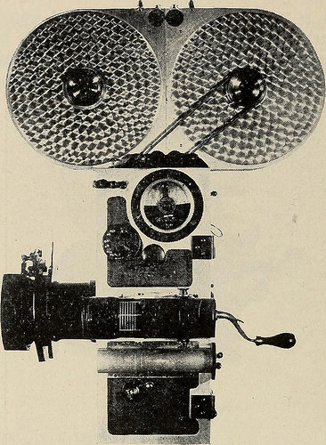
Image from page 87 of “Transactions of the Society of Motion Picture Engineers (1921)” (1921)
precision engineering companies
Image by Internet Archive Book Images
Identifier: transactionsofso12soci_0
Title: Transactions of the Society of Motion Picture Engineers (1921)
Year: 1921 (1920s)
Authors: Society of Motion Picture Engineers
Subjects: motion pictures
Publisher: Society of Motion Picture Engineers
Contributing Library: Library of Congress, MBRS, Moving Image Section
Digitizing Sponsor: Library of Congress, Motion Picture, Broadcasting and Recorded Sound Division

View Book Page: Book Viewer
About This Book: Catalog Entry
View All Images: All Images From Book

Click here to view book online to see this illustration in context in a browseable online version of this book.

Text Appearing Before Image:
of f3.5 and is set in an accurate focusing mount. The new model of the professional Debrie Camera appears out-wardly much the same as formerly, but is now equipped with auto-matic shutter dissolve and a number of minor refinements in con-struction and design. The French Pathe Camera remains practically the same asbefore the war but the American Pathe which is the name frequentlyapplied to the Wilart Camera, has forged ahead so consistenly thatthe old simile no longer applies. Even the old familiar form of the studio model with overheadexterior magazines will soon become a thing of the past for the newmodel of the Wilart Camera which will appear shortly has lines dis-tinctively its own and the magazines will be placed inside the camera so that it can be taken from its case threaded ready for operation. Some of the advantages of the present Wilart model over thePathe are as follows: all metal construction, automatic shutter dis-solve, all metal film race, automatic opening light traps,

Text Appearing After Image:
Side elevation of Wilart Camera. view finder, improved focusing mechanism, ball bearings, Veedercounter, interior masks, etc. The Wilart Instrument Company is about to put on the marketa small motion picture camera using half width film for home usewhich they expect will have many commercial applications as well.This camera, called the Arcograph, looks like a miniature model ofthe Bell & Howell and is made with the same care and precision asa professional camera. The pictures made by this little instrumentare one-quarter the standard size and the projector of portable typewith a reel of film ready threaded is about the size of a lunch boxor a bag for a mans bathing suit. The Universal Camera sold by Burke & James now has anautomatic shutter dissolve built into the camera and a turret attach-ment for carrying extra lenses is now available. The American Motion Picture Machine Company of LongIsland City have recently brought out a turret for four lenses whichthey attach to the Pa

Note About Images
Please note that these images are extracted from scanned page images that may have been digitally enhanced for readability – coloration and appearance of these illustrations may not perfectly resemble the original work.
Good Machining Engineering images

Good Machining Engineering images

A couple of nice machining engineering images I identified:

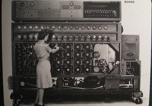
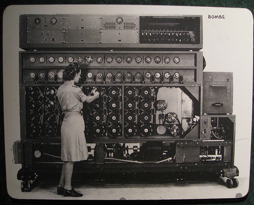
US Navy Cryptanalytic Bombe
machining engineering
Image by brewbooks
A US Navy WAVE sets the Bombe rotors prior to a run

The US NAvy cryptanalytic Bombes had only one particular purpose: Decide the rotor settings utilized on the German cipher machine ENIGMA. Initially created by Joseph Desch with the National Cash Register Firm in Dayton, Ohio, the Bombes worked mainly against the German Navy’s four-rotor ENIGMAs. Without the correct rotor settings, the messages were practically unbreakable. The Bombes took only twenty minutes to complete a run, testing the 456,976 feasible rotor settings with a single wheel order. Various Bombes attempted various wheel orders, and a single of them would have the final appropriate settings. When the a variety of U-boat settings have been identified, the Bombe could be switched over to operate on German Army and Air Force 3-rotor messages.
Supply: National Cryptologic Museum

Comment on the above
The 4 rotor program had 26^4 or 456,976 settings whilst the theree rotor technique had 26^three or 17,756 settings. It appears like the dilemma scale in a linear way as it took 50 seconds to verify 17,756 setting (~350 per second) whilst the 4 rotor resolution in 20 minutes is ~ 380 settings per second.

I also think the designer Joseph Desch sounds like a remarkable engineer that I never ever heard of just before.

Bombe on Wikipedia
As soon as the British had offered the Americans the information about the bombe and its use, the US had the National Cash Register Company manufacture a great several extra bombes, which the US then utilised to help in the code-breaking. These ran significantly quicker than the British version, so quick that as opposed to the British model, which would freeze quickly (and ring a bell) when a attainable answer was detected, the NCR model, upon detecting a feasible remedy, had to &quotremember&quot that setting and then reverse its rotors to back up to it (meanwhile the bell rang).

Source of following material : National Cryptologic Museum

Diagonal Board is the heart of the Bombe unit. Electrically, it has 26 rows and 26 columns of points, each with a diagonal wire connection. These wires connect every single letter in a column with the exact same position in each and every row. A letter cannot plug into itself these are recognized as &quotself-steckers.&quot The resulting pattern is a series of diagonal lines. The purpose of the diagonal board is to eliminate the complications brought on by the Enigma’s plugboard. Provided particular rotor settings, only specific plugboard settings can result in the proper encrypted letter. The diagonal board disproved hundreds of rotor settings, permitting for only a handful of possibly right settings to outcome in a &quotstrike&quot.

Amplifier Chassis had two purposes, very first to detect a hit and second to decide if it was useful. It supplied the tie-in from the diagonal board, the locator, and the printer circuits.

Thyratron Chassis was the machine’s memory. Considering that the wheels spun at such a high speed, they could not instantly quit rotating when a correct hit was detected. The Thyratron remembered exactly where the appropriate hit was located and indicated when the Bombe has rewound to that position. It also told the machine when it had completed a run and gave the final stop signal.

Switch Banks tell the Bombe what plain to cipher letters to search for. Utilizing menus sent to the Bombe deck by cryptanalysts, WAVES set each dial making use of unique wrenches. 00 equates to the letter A and 25 to the letter Z. The dials work together in groups of two. 1 dial is set to the plain test letter and the other to its corresponding cipher letter as determined by cryptanalysts. There are sixteen sets of switch banks, however, only fourteen had been required to comprehensive a run. As the machine worked through the rotor settings, a correct hit was possible if the electrical path in all fourteen switch banks corresponded to every of their assigned plaintext/cipher combinations.

Wheel Banks represent the 4 rotors used on the German U-boat Enigma. Every column interconnects the 4 rotors, or commutators, in that column. The leading commutator represented the fourth, or slowest, rotor on the Enigma, although the bottom wheel represented the rightmost, or fastest, rotor. The WAVES set the rotors according to the menu developed by the cryptanalysts. The 1st have been set to 00, and each set soon after that corresponded to the plain/cipher hyperlink with the crib (the assumed plain test corresponding to the cipher text.) Normally this meant that each wheel bank stepped up one spot from the 1 on its left. When the machine ran, each bottom rotor stepped forward, and the machine electrically checked to see if the assigned situations had been met. If not, as was generally the case, every bottom wheels moved 1 a lot more place forward. Nonetheless, the bottom commutator moved at 850 rpm, so it only took twenty minutes to full a run of all 456,976 positions.

Printer automatically printed the details of a attainable hit. When the Bombe determined that all the possible conditions had been met. it printed wheel order, rotor settings and plugboard connections.

Motor Manage Chassis controlled both forward and reverse motors. The Bombe was an electromechanical machine and needed a number of gauges for monitoring. It also necessary a Braking Assembly to slow the forward motion when a hit was detected and to bring the machine to a complete quit when a run was completed.

i09_0214 129

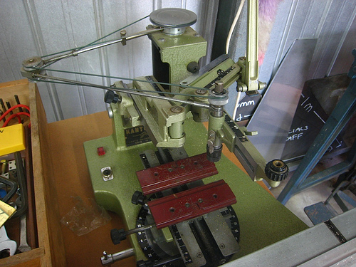
Engraving machine
machining engineering
Image by brotherlywalks

Cool Cnc Engineering Services photos

Cool Cnc Engineering Services photos

A few nice cnc engineering solutions images I found:

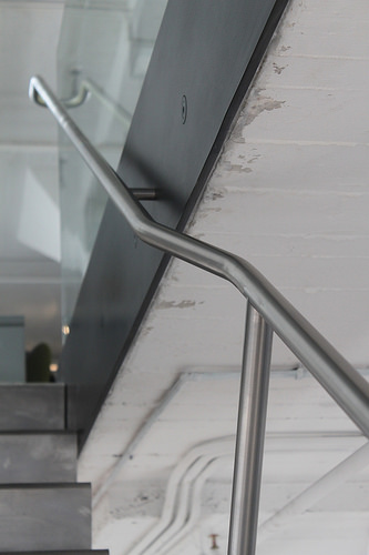
Handrail Jog
cnc engineering services
Image by Caliper Studio
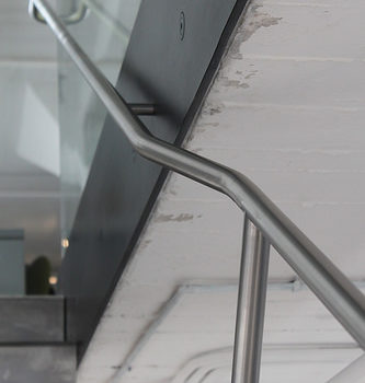
Center stringer comfort stair connects two office floors in Starret Lehigh developing. Stringer and slab edge assemblies are blackened. Twenty four stainless steel treads are welded to the stringer type a continuous ribbon. 1 1/4&quot diameter handrail posts are continuous bent &quotC&quot shapes that wrap about treds and are welded to stringer. Stair was delivered to internet site in one particular piece [24′ extended 3′ wide 3′ tall @ 2000lbs. Glass is two 1/2&quot layers of low iron tempered glass with PVB interlayer. Every panel is a 148.375&quotx41.25&quot rectangle that weighs 522lbs. Cut out in concrete floor is trimmed with a box of 1/2&quot thick blackened steel that was fully prewelded in the shop. The box picks up the load at best of stair and serves as a custom base shoe for the glass.

Style by Diller Scofidio + Renfro

Detailing, Fabrication and Installation by Caliper Studio. Caliper Studio engaged Eckersley O’Callaghan &amp partners for engineering solutions.

Cool Prototype Engineering pictures

Cool Prototype Engineering pictures

Check out these prototype engineering pictures:

Silver and Gold
prototype engineering
Image by NASA Goddard Photo and Video
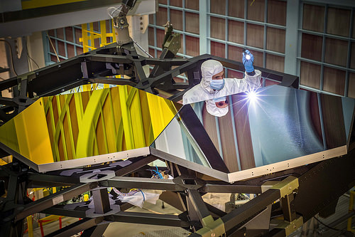
Inside NASA’s Goddard Space Flight Center’s giant clean area in Greenbelt, Md., JWST Optical Engineer Larkin Carey from Ball Aerospace, examines two test mirror segments recently placed on a black composite structure. This black composite structure is referred to as the James Webb Space Telescope’s “Pathfinder” and acts as a spine supporting the telescope’s principal mirror segments. The Pathfinder is a non-flight prototype.

The mirrors had been placed on Pathfinder employing a robotic arm move that involved hugely trained engineers and technicians from Exelis, Northrop Grumman and NASA.

&quotGetting this right is crucial to proving we are prepared to commence assembling the flight mirrors onto the flight structure next summer season,&quot stated Lee Feinberg, NASA’s Optical Telescope Element Manager at NASA Goddard. &quotThis is the first space telescope that has ever been built with a light-weighted segmented main mirror, so studying how to do this is a groundbreaking capability for not only the Webb telescope but for potential future space telescopes.&quot

The James Webb Space Telescope is the successor to NASA’s Hubble Space Telescope. It will be the most strong space telescope ever built. Webb is an international project led by NASA with its partners, the European Space Agency and the Canadian Space Agency.

For much more info about the Webb telescope, go to: www.jwst.nasa.gov or www.nasa.gov/webb

Credit: NASA/Chris Gunn

NASA image use policy.
NASA Goddard Space Flight Center enables NASA’s mission by means of four scientific endeavors: Earth Science, Heliophysics, Solar Method Exploration, and Astrophysics. Goddard plays a major function in NASA’s accomplishments by contributing compelling scientific understanding to advance the Agency’s mission.
Adhere to us on Twitter
Like us on Facebook
Locate us on Instagram

Ivatt tiny Atlantic 990, Henry Oakley
prototype engineering
Image by Snapshooter46
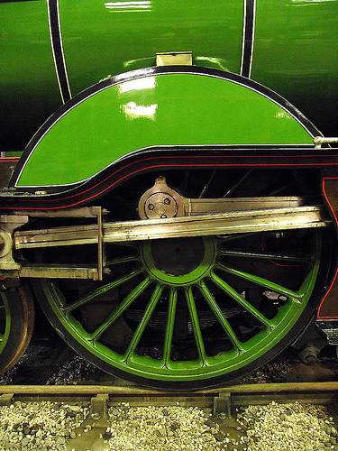
The Wonderful Northern Railway Small Boiler Class C1. The first four-four-two (Atlantic) sort in Fantastic Britain. Created by Henry Ivatt in 1897, 22 have been built among 1898 and 1903 at Doncaster Works. It was outshopped a couple of month’s ahead of Aspinall’s prototype Atlantic for the Lancashire &amp Yorkshire Railway.

Prototype
prototype engineering
Image by Hugh Dutton Associés
Louvre Islamic Arts Museum – Paris, France
HDA : Technical design and style &amp Engineering
Client : Etablissement Public du Musée du Louvre
Architect: Mario Bellini &amp Rudy Ricciotti
Date : 2006 – 2012
See more at : www.hda-paris.com/

Cool Mechanical Engineering China photos

Cool Mechanical Engineering China photos

A couple of nice mechanical engineering china images I found:

Image from web page 615 of “Railway mechanical engineer” (1916)
mechanical engineering china
Image by Net Archive Book Pictures
Identifier: railwaymechanica95newy
Title: Railway mechanical engineer
Year: 1916 (1910s)
Authors:
Subjects: Railroad engineering Engineering Railroads Railroad vehicles
Publisher: New York, N.Y. : Simmons-Boardman Pub. Co
Contributing Library: Carnegie Library of Pittsburgh
Digitizing Sponsor: Lyrasis Members and Sloan Foundation

View Book Page: Book Viewer
About This Book: Catalog Entry
View All Pictures: All Pictures From Book

Click right here to view book on the internet to see this illustration in context in a browseable online version of this book.

Text Appearing Just before Image:
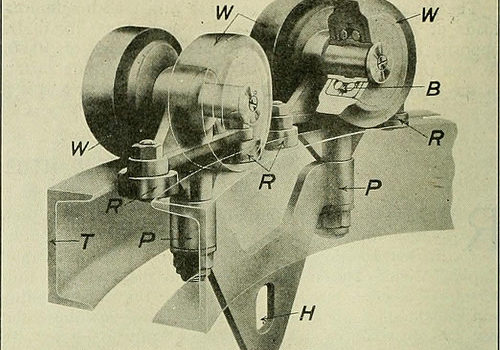
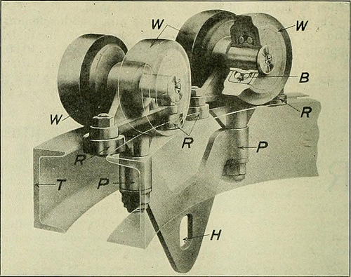
s into an open freightcar or automobile truck. The method can also be readilywired ought to an electric hoist be desired in spot of chainfalls. The track is built and shipped and can be erected assingle units, thus drastically lowering the price of erection. Specific two-wheel, four-wheel, or eight-wheel trolleys are supplied,the four-wheel type being illustrated in Fig. 2. There are ball-bearing wheels W and guide rollers R which run betweenthe toes of the channels, practically eliminating friction andmaking it difficult for the wheels to bind against the track ,&ampmtm WS^J! JB49JP ^five | wzw m m Fig. 1—View of Overhead Trolley Method with Universal Switches when rounding the curves. Carbonized steel ball bearingsare shown at B, pivots at P and the hoist connection at H.The trolley runs on the level leading of the channel tracks and is designed to swing in the identical 18 in. radius curves. Thefact that this track is built from standard rolled channelsor can be built from I-beam sections exactly where long spans and

Text Appearing After Image:
Fig. 2—Phantom View of Short Turn Trolley greater strength is necessary, tends to make it straightforward to obtain fromlocal stocks and less complicated to erect. The operation of this systemlightens the function and makes it considerably a lot more easy and favorablefor the workmen handling material, thereby decreasing laborturnover and rising the efficiency of unskilled labor.The system is being manufactured and sold by the WhitingCorporation, Harvey, 111. Unique Hydraulic Driving Wheel Press THE Hydraulic Press Manufacturing Firm, MountGilead, Ohio, designed and built the particular hydraulicpress, illustrated, which was lately sold by the Mc-Carter Cooper Business, New York, to the Compagnie Gen-eral De Chemins De Fer &amp Tramways en Chine, Pekin,China. This press is employed for forcing driving wheels on or off amongst strain bars is 84 in. and in between ram and resistancehead is 108 in. maximum. This may possibly be decreased to 78 in.by moving the resistance head, which is mounted on wheels.The press is also equipped with a belt

Note About Photos
Please note that these photos are extracted from scanned page photos that might have been digitally enhanced for readability – coloration and appearance of these illustrations may possibly not perfectly resemble the original perform.

Image from web page 67 of “Railway mechanical engineer” (1916)
mechanical engineering china
Image by World wide web Archive Book Pictures
Identifier: railwaymechanica93newy
Title: Railway mechanical engineer
Year: 1916 (1910s)
Authors:
Subjects: Railroad engineering Engineering Railroads Railroad automobiles
Publisher: New York, N.Y. : Simmons-Boardman Pub. Co
Contributing Library: Carnegie Library of Pittsburgh
Digitizing Sponsor: Lyrasis Members and Sloan Foundation

View Book Page: Book Viewer
About This Book: Catalog Entry
View All Images: All Images From Book

Click right here to view book on the web to see this illustration in context in a browseable on the internet version of this book.

Text Appearing Before Image:
ult, nowadays the Continental—European—design of locomotive is predominant in China.On some of the lines, notably these beneath English and,hitherto, German influence, not a locomotive other than thosebuilt in accordance with the prevailing design frequent tothe nation financing the railway was bought or even con-sidered, either for initial or sub.sequent equipment—at leastup to the time of the outbreak of the war. Only in the caseof the Chinese financed and operated railway have Ameri-can builders been offered a cost-free hand, with the result that anAmerican design and style was adopted, and a thorough standardiza-tion of energy effected. Out of the 638 locomotives in ser-vice on all lines at that time only 15 five/2 per cent had been ofAmerican desi.gn and manufacture and on the Engli.sh,Belgian, and French lines, which operated at that time 365locomotives, or around 60 per cent of the total, onlveight, or approximately 2.2 per cent had been of American de-sign and manufacture.—Eastern Engineering.

Text Appearing Soon after Image:
THE BLOMQUIST-ECK HORIZONTALBORING MILL The operating efficiency of any horizontal mill and drilldepends entirely upon its potential to operate upon all classesof work at the highest speeds and coarsest feeds practicable,and at all occasions to generate a completed product of dependableaccuracy. The Blomquist-Eck Machine Firm, Cleve-land, Ohio, in designing its new horizontal boring mill, hasdeveloped these points to a higher degree by combiningrigidity, accuracy, a suitable range of selective speeds and

Note About Pictures
Please note that these pictures are extracted from scanned page photos that may have been digitally enhanced for readability – coloration and look of these illustrations may not completely resemble the original work.
Good Precision Engineering Services images

Good Precision Engineering Services images

Some cool precision engineering solutions pictures:

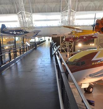
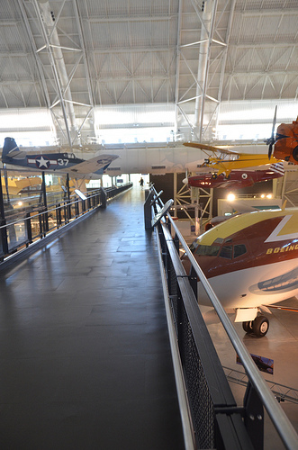
Steven F. Udvar-Hazy Center: south hangar panorama, including Grumman F6F-three Hellcat, North American P-51C “Excalibur III”, Grumman G-22 “Gulfhawk II”, Boeing 367-80 (707) Jet Transport among other folks
precision engineering services
Image by Chris Devers
Quoting Smithsonian National Air and Space Museum | Grumman F6F-three Hellcat:

The Grumman F6F Hellcat was originally conceived as an advanced version of the U.S. Navy’s then current front-line fighter, the F4F Wildcat (see NASM collection). The Wildcat’s intended replacement, the Vought F4U Corsair (see NASM collection), 1st flown in 1940, was showing excellent guarantee, but improvement was slowed by issues, including the crash of the prototype.

The National Air and Space Museum’s F6F-3 Hellcat, BuNo. 41834, was constructed at Grumman’s Bethpage, New York, factory in February 1944 below contract NOA-(S)846. It was delivered to the Navy on February 7, and arrived in San Diego, California, on the 18th. It was assigned to Fighter Squadron 15 (VF-15) on USS Hornet (CV12) bound for Hawaii. On arrival, it was assigned to VF-3 where it sustained harm in a wheels-up landing at NAS Barbers Point, Hawaii. Soon after repair, it was assigned to VF-83 where it was utilized in a training part till February 21, 1945. Following numerous transfers 41834 was converted to an F6F-3K target drone with the installation of sophisticated radio-manage equipment. It was painted red with a pink tail that carried the number 14. Its mission was to be utilised in Operation Crossroads – the atomic bomb tests at Bikini Atoll. It flew on June 24, 1946, with a pilot, on a practice flight and was launched, unmanned, quickly after the 1st bomb test. Instrumentation on board and photographic plates taped to the control stick obtained data on radioactivity. 3 much more manned flights preceded the final unmanned flight on July 25, 1946, which evaluated the very first underwater explosion. Records indicate that exposure of this aircraft to the radioactive cloud was minimal and residual radiation is negligible.

F6F-3K 41834 was transferred to NAS Norfolk and logged its last flight on March 25, 1947, with a total of 430.2 flying hours. It was assigned to the National Air Museum on November three, 1948, and remained at Norfolk until October 4, 1960, when it was moved by barge to Washington and placed in storage. In 1976 this Hellcat was loaned to the USS Yorktown Museum at Charleston, South Carolina. A superficial restoration was performed at the museum, but due to the fact of the harsh atmosphere and its poor condition the Hellcat was returned to NASM on March 16, 1982. In 1983, it was sent to Grumman Aerospace exactly where a group of volunteers totally restored the aircraft. In 1985, it was shipped back to the Paul E. Garber Preservation, Restoration and Storage Facility in Suitland, Maryland, and place in storage. NASM’s F6F-three Hellcat is scheduled to be displayed in the new Steven F. Udvar-Hazy center at Dulles International Airport in Virginia in 2004.

Transferred from the United States Navy.

Manufacturer:
Grumman Aircraft Engineering Corporation

Date:
1943

Country of Origin:
United States of America

Dimensions:
Overall: 338 x 1021cm, 4092kg, 1304cm (11ft 1 1/16in. x 33ft five 15/16in., 9021.2lb., 42ft 9 three/8in.)

Physical Description:
Heavy armor plate, reinforced empennage, R-2800-10W engine, spring tabs on the ailerons (enhanced maneuverability), could carry rockets as properly as bombs.

• • • • •

Quoting Smithsonian National Air and Space Museum | North American P-51C, &quotExcalibur III&quot:

On May 29, 1951, Capt. Charles F. Blair flew Excalibur III from Norway across the North Pole to Alaska in a record-setting 10½ hours. Employing a technique of meticulously plotted &quotsun lines&quot he developed, Blair was in a position to navigate with precision where conventional magnetic compasses often failed. Four months earlier, he had flown Excalibur III from New York to London in significantly less than 8 hours, breaking the existing mark by more than an hour.

Excalibur III 1st belonged to famed aviator A. Paul Mantz, who added extra fuel tanks for lengthy-distance racing to this standard P-51C fighter. With it Mantz won the 1946 and 1947 Bendix air race and set a transcontinental speed record in 1947 when the airplane was named Blaze of Noon. Blair bought it from Mantz in 1949 and renamed it Excalibur III, after the Sikorsky VS-44 flying boat he flew for American Export Airlines.

Present of Pan American Planet Airways

Manufacturer:
North American Aircraft Firm

Date:
1944

Country of Origin:
United States of America

Dimensions:
Wingspan: 11.three m (37 ft)
Length: 9.eight m (32 ft three in)
Height: three.9 m (12 ft 10 in)
Weight, empty: four,445 kg (9,800 lb)
Weight, gross: 5,052 kg (11,800 lb)
Best speed: 700 km/h (435 mph)

Materials:
Overall: Aluminum

Physical Description:
Single seat, single engine, low wing monoplane, Planet War II fighter modified for racing.

• • • • •

Quoting Smithsonian National Air and Space Museum | Grumman G-22 &quotGulfhawk II&quot:

One particular of the most fascinating aerobatic aircraft of the 1930s and ’40s, the Grumman Gulfhawk II was constructed for retired naval aviator and air show pilot Al Williams. As head of the Gulf Oil Company’s aviation division, Williams flew in military and civilian air shows around the country, performing precision aerobatics and dive-bombing maneuvers to market military aviation during the interwar years.

The sturdy civilian biplane, with its strong aluminum monocoque fuselage and Wright Cyclone engine, nearly matched the Grumman F3F standard Navy fighter, which was operational at the time. It took its orange paint scheme from Williams’ Curtiss 1A Gulfhawk, also in the Smithsonian’s collection. Williams personally piloted the Gulfhawk II on its final flight in 1948 to Washington’s National Airport.

Present of Gulf Oil Corporation

Manufacturer:
Grumman Aircraft Engineering Corporation

Date:
1936

Nation of Origin:
United States of America

Dimensions:
Wingspan: 8.7 m (28 ft 7 in)
Length: 7 m (23 ft)
Height: three.1 m (10 ft)
Weight, aerobatic: 1,625 kg (3,583 lb)
Weight, gross: 1,903 kg (4,195 lb)
Prime speed: 467 km/h (290 mph)
Engine: Wright Cyclone R-1820-G1, 1,000 hp

Components:
Fuselage: steel tube with aluminum alloy
Wings: aluminum spars and ribs with fabric cover

Physical Description:
NR1050. Aerobatic biplane flown by Key Alford &quotAl&quot Williams as demonstration aircraft for Gulf Oil Business. Similar to Grumman F3F single-seat fighter aircraft flown by the U.S. Navy. Wright Cyclone R-1820-G1 engine, 1000 hp.

• • • • •

Quoting Smithsonian National Air and Space Museum | Boeing 367-80 Jet Transport:

On July 15, 1954, a graceful, swept-winged aircraft, bedecked in brown and yellow paint and powered by 4 revolutionary new engines initial took to the sky above Seattle. Built by the Boeing Aircraft Company, the 367-80, far better recognized as the Dash 80, would come to revolutionize commercial air transportation when its created version entered service as the well-known Boeing 707, America’s initial jet airliner.

In the early 1950s, Boeing had begun to study the possibility of generating a jet-powered military transport and tanker to complement the new generation of Boeing jet bombers entering service with the U.S. Air Force. When the Air Force showed no interest, Boeing invested million of its personal capital to create a prototype jet transport in a daring gamble that the airlines and the Air Force would buy it after the aircraft had flown and confirmed itself. As Boeing had accomplished with the B-17, it risked the business on one particular roll of the dice and won.

Boeing engineers had initially primarily based the jet transport on studies of improved designs of the Model 367, much better recognized to the public as the C-97 piston-engined transport and aerial tanker. By the time Boeing progressed to the 80th iteration, the design and style bore no resemblance to the C-97 but, for safety reasons, Boeing decided to let the jet project be identified as the 367-80.

Function proceeded rapidly following the formal commence of the project on May 20, 1952. The 367-80 mated a large cabin primarily based on the dimensions of the C-97 with the 35-degree swept-wing design and style based on the wings of the B-47 and B-52 but considerably stiffer and incorporating a pronounced dihedral. The wings were mounted low on the fuselage and incorporated high-speed and low-speed ailerons as nicely as a sophisticated flap and spoiler method. Four Pratt &amp Whitney JT3 turbojet engines, every single creating 10,000 pounds of thrust, had been mounted on struts beneath the wings.

Upon the Dash 80’s 1st flight on July 15, 1954, (the 34th anniversary of the founding of the Boeing Firm) Boeing clearly had a winner. Flying 100 miles per hour quicker than the de Havilland Comet and substantially larger, the new Boeing had a maximum range of much more than three,500 miles. As hoped, the Air Force bought 29 examples of the design and style as a tanker/transport right after they convinced Boeing to widen the style by 12 inches. Satisfied, the Air Force designated it the KC-135A. A total of 732 KC-135s have been constructed.

Speedily Boeing turned its interest to selling the airline business on this new jet transport. Clearly the sector was impressed with the capabilities of the prototype 707 but never far more so than at the Gold Cup hydroplane races held on Lake Washington in Seattle, in August 1955. For the duration of the festivities surrounding this event, Boeing had gathered numerous airline representatives to appreciate the competitors and witness a fly past of the new Dash 80. To the audience’s intense delight and Boeing’s profound shock, test pilot Alvin &quotTex&quot Johnston barrel-rolled the Dash 80 more than the lake in full view of thousands of astonished spectators. Johnston vividly displayed the superior strength and overall performance of this new jet, readily convincing the airline business to get this new airliner.

In searching for a market place, Boeing discovered a prepared buyer in Pan American Airway’s president Juan Trippe. Trippe had been spending considerably of his time browsing for a suitable jet airliner to allow his pioneering business to keep its leadership in international air travel. Functioning with Boeing, Trippe overcame Boeing’s resistance to widening the Dash-80 style, now identified as the 707, to seat six passengers in every single seat row rather than five. Trippe did so by placing an order with Boeing for 20 707s but also ordering 25 of Douglas’s competing DC-8, which had yet to fly but could accommodate six-abreast seating. At Pan Am’s insistence, the 707 was created 4 inches wider than the Dash 80 so that it could carry 160 passengers six-abreast. The wider fuselage created for the 707 became the regular design and style for all of Boeing’s subsequent narrow-body airliners.

Even though the British de Havilland D.H. 106 Comet and the Soviet Tupolev Tu-104 entered service earlier, the Boeing 707 and Douglas DC-eight had been larger, faster, had greater variety, and had been much more profitable to fly. In October 1958 Pan American ushered the jet age into the United States when it opened international service with the Boeing 707 in October 1958. National Airlines inaugurated domestic jet service two months later using a 707-120 borrowed from Pan Am. American Airlines flew the 1st domestic 707 jet service with its own aircraft in January 1959. American set a new speed mark when it opened the 1st frequently-scheduled transcontinental jet service in 1959. Subsequent nonstop flights between New York and San Francisco took only 5 hours – 3 hours significantly less than by the piston-engine DC-7. The one-way fare, such as a surcharge for jet service, was 5.50, or 1 round trip. The flight was nearly 40 % faster and virtually 25 % cheaper than flying by piston-engine airliners. The consequent surge of traffic demand was substantial.

The 707 was initially created for transcontinental or a single-stop transatlantic range. But modified with added fuel tanks and far more effective turbofan engines, the 707-300 Intercontinental series aircraft could fly nonstop across the Atlantic with full payload beneath any conditions. Boeing constructed 855 707s, of which 725 had been purchased by airlines worldwide.

Obtaining launched the Boeing Organization into the industrial jet age, the Dash 80 soldiered on as a very effective experimental aircraft. Till its retirement in 1972, the Dash 80 tested numerous sophisticated systems, a lot of of which had been incorporated into later generations of jet transports. At one particular point, the Dash 80 carried 3 different engine sorts in its four nacelles. Serving as a test bed for the new 727, the Dash 80 was briefly equipped with a fifth engine mounted on the rear fuselage. Engineers also modified the wing in planform and contour to study the effects of distinct airfoil shapes. Many flap configurations were also fitted including a highly sophisticated method of &quotblown&quot flaps which redirected engine exhaust over the flaps to improve lift at low speeds. Fin height and horizontal stabilizer width was later elevated and at one point, a specific several wheel low pressure landing gear was fitted to test the feasibility of operating future heavy military transports from unprepared landing fields.

After a long and distinguished profession, the Boeing 367-80 was ultimately retired and donated to the Smithsonian in 1972. At present, the aircraft is installated at the National Air and Space Museum’s new facility at Washington Dulles International Airport.

Gift of the Boeing Organization

Manufacturer:
Boeing Aircraft Co.

Date:
1954

Nation of Origin:
United States of America

Dimensions:
Height 19′ 2&quot: Length 73′ 10&quot: Wing Span 129′ eight&quot: Weight 33,279 lbs.

Physical Description:
Prototype Boeing 707 yellow and brown.

Cool Prototype Engineering images

Cool Prototype Engineering images

Verify out these prototype engineering pictures:

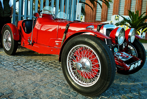
Riley Brooklands 1930
prototype engineering
Image by pedrosimoes7
Belem, Lisbon, Portugal

in Wikipedia

Riley was a British motorcar and bicycle manufacturer from 1890. The business became element of the Nuffield Organisation in 1938 and was later merged into British Leyland: late in 1969 British Leyland announced their discontinuance of Riley production, even though 1969 was a hard year for the UK auto market and so a quantity of automobiles from the company’s inventory are most likely to have been first registered only in 1970.[2]
These days, the Riley trademark is owned by BMW.

Riley Cycle Firm

Riley started as the Bonnick Cycle Organization of Coventry, England. During the pedal cycle craze that swept Britain at the end of the nineteenth century, in 1890, William Riley Jr. purchased the organization and in 1896 renamed it the Riley Cycle Firm.[2] Later, cycle gear maker Sturmey Archer was added to the portfolio. Riley’s younger son, Percy, left college in the identical year and quickly began to dabble in automobiles. He constructed his first car at 16, in 1898, secretly, simply because his father did not approve. It featured the very first mechanically operated inlet valve. By 1899, Percy Riley moved from making motorcycles to his very first prototype four-wheeled quadricycle. Small is recognized about Percy Riley’s really very first &quotmotor-vehicle&quot. It is, however, nicely attested that the engine featured mechanically operated cylinder valves at a time when other engines depended on the vacuum effect of the descending piston to suck the inlet valve(s) open. That was demonstrated some years later when Benz created and patented a mechanically operated inlet valve approach of their personal but had been unable to collect royalties on their system from British companies the courts were persuaded that the technique utilised by British auto-makers was primarily based the one pioneered by Percy, which had comfortably anticipated equivalent developments in Germany.[2] In 1900, Riley sold a single 3-wheeled automobile. Meanwhile the elder of the Riley brothers, Victor Riley, despite the fact that supportive of his brother’s embryonic motor-vehicle enterprise, devoted his energies at this stage to the core bicycle company.[2]

Company founder William Riley remained resolutely opposed to diverting the resources of his bicycle business into motor vehicles, and in 1902 three of his sons, Victor, Percy and younger brother Alan Riley pooled resources, borrowed a essential balancing amount from their mother and in 1903 established the separate Riley Engine Firm, also in Coventry.[2] A few years later the other two Riley brothers, Stanley and Cecil, possessing left college joined their elder brothers in the business.[two] At 1st, the Riley Engine Firm basically supplied engines for Riley motorcycles and also to Singer, a newly emerging motor cycle manufacturer in the location,[two] but the Riley Engine Firm organization quickly began to concentrate on 4-wheeled automobiles. Their Vee-Twin Tourer prototype, produced in 1905, can be deemed the 1st proper Riley vehicle. The Engine Company expanded the subsequent year. William Riley reversed his former opposition to his sons’ preference for motorised vehicles and Riley Cycle halted motorcycle production in 1907 to concentrate on automobiles.[two] Bicycle production also ceased in 1911.

In 1912, the Riley Cycle Company changed its name to Riley (Coventry) Limited as William Riley focused it on becoming a wire-spoked wheel supplier for the burgeoning motor business, the detachable wheel having been invented (and patented) by Percy and distributed to more than 180 motor manufacturers, and by 1912 the father’s enterprise had also dropped automobile manufacture in order to concentrate capacity and resources on the wheels. Exploitation of this new and swiftly expanding lucrative business sector made commercial sense for William Riley, but the abandonment of his motor-bicycle and then of his automobile enterprise which had been the principal consumer for his sons’ Riley Engine Organization enforced a rethink on the Engine Firm.[2]

Riley Motor Manufacturing

In early 1913, Percy was joined by three of his brothers (Victor, Stanley, and Allan) in a new business focused on manufacturing whole automobiles. This Riley Motor Manufacturing Firm was situated close to Percy’s Riley Engine Business. The 1st new model, the 17/30, was introduced at the London Motor Show that year. Quickly afterwards, Stanley Riley founded however another business, the Nero Engine Organization, to create his own 4-cylinder 10 hp (7.5 kW) car. Riley also began manufacturing aeroplane engines and became a essential supplier in Britain’s buildup for Planet War I.

In 1918, soon after the war, the Riley businesses had been restructured. Nero joined Riley (Coventry) as the sole producer of automobiles. Riley Motor Manufacturing came beneath the handle of Allan Riley to become Midland Motor Bodies, a coachbuilder for Riley. Riley Engine Organization continued under Percy as the engine supplier. At this time, Riley’s blue diamond badge, developed by Harry Rush, also appeared. The motto was &quotAs old as the industry, as modern as the hour.

Riley grew swiftly by way of the 1920s and 1930s. Riley Engine developed four-, 6-, and 8-cylinder engines, although Midland constructed far more than a dozen diverse bodies. Riley models at this time incorporated:
Saloons: Adelphi, Continental, Deauville, Falcon, Kestrel, Mentone, Merlin, Monaco, Stelvio, Victor
Coupes: Ascot, Lincock
Touring: Alpine, Lynx, Gamecock
Sports: Brooklands, Imp, MPH, Sprite
Limousines: Edinburgh, Winchester

The Riley Brooklands was 1 of the most successful performs and privateer racing automobiles of the late 1920s and early 1930s, specifically in hill climbs and at Le Mans, delivering a platform for the good results of motorsports’ 1st women racing drivers like Kay Petrie and Dorothy Champney. It was primarily based on Percy Riley’s ground-breaking Riley 9 engine, a modest capacity, high revving engine, ahead of its time in numerous respects. It had a hemispherical combustion chamber and overheard valves and has been called the most considerable engine improvement of the 1920s. Its longevity is illustrated by Mike Hawthorn’s early racing good results right after WW2 in pre-war Rileys, in certain his father’s Sprite. But by about 1936 the firm had overextended, with too many models and as well few frequent parts, and the emergence of Jaguar at Coventry was a direct challenge. Victor Riley had set up a new ultra-luxury concern, Autovia, to generate a V8 saloon and limousine to compete with Rolls-Royce. Meanwhile, Riley Engine Company had been renamed PR Motors (after Percy Riley) to be a higher-volume supplier of engines and components. Although the rest of the Riley companies would go on to turn into part of BMC, PR Motors remained independent. Following the death of Percy Riley in 1941, the firm began generating transmission components and still exists nowadays as Newage Transmissions. Percy’s widow Norah ran the organization for a lot of years and was Britain’s businesswoman of the year in 1960.

Nuffield Organisation

By 1937, Riley started to appear to other makers for partnerships. It had withdrawn from performs racing soon after its most successful year, 1934, although it continued to provide engines for the ERA, a voiturette (Formula 2) racing vehicle based on the supercharged 6-cylinder ‘White Riley’, developed by ERA founder Raymond Mays in the mid-thirties. Rileys (Ulster Imp and Sprite) had been also the 1st important automobiles raced by Mike Hawthorn following the war. BMW of Munich, Germany was interested in expanding its range into England. But the Rileys were much more interested in a larger British concern, and looked to Triumph Motor Business, also of Coventry, as a all-natural fit. In February, 1938, all negotiations collapsed as Riley (Coventry) and Autovia went into receivership.
Each firms had been bought by Lord Nuffield for £143,000 and operated by Victor Riley as Riley (Coventry) Successors. It was rapidly sold to Nuffield’s Morris Motor Organization for £1, with the combination coming to be called the Nuffield Organisation.
Nuffield took swift measures to firm up the firm. Autovia was no more, with just 35 automobiles getting been made. Riley refocused on the four-cylinder market place with two engines: A 1.five litre 12 hp engine and the &quotBig 4&quot, a 2.5 litre 16 hp unit (The hp figures are RAC Rating, and bear no partnership to bhp or kW). Only a couple of bodies have been made, and some elements had been shared with Morris for economies of scale.
After World War II, the restarted Riley Motors took up the old engines in new models, based in conception on the 1936-8 ‘Continental’. The RMA employed the 1.five litre engine, whilst the RMB got the Large Four. The RM line of cars, sold under the &quotMagnificent Motoring&quot tag line, have been to be the company’s higher point. They featured a front independent suspension and steering program inspired by the Citroën Traction Avant. Their flowing lines have been particularly nicely-balanced, marrying pre-war ‘coachbuilt’ elegance to far more contemporary attributes, such as headlamps faired-in to the front wings.

Victor Riley was removed by Nuffield in 1947, and the Coventry works had been shut down as production was consolidated with MG at Abingdon. Nuffield’s marques had been to be organised in a related way to these of Basic Motors: Morris was to be the value line, MG provided overall performance, and Wolseley was to be the luxury marque. But with the luxury marque, and sporty/luxurious Riley also fighting for the leading position, the range was crowded and confused.

British Motor Corporation

The confusion became critical in 1952 with the merger of Nuffield and Austin as the British Motor Corporation. Now, Riley was positioned in between MG and Wolseley and most Riley models have been, like these, little more than badge-engineered versions of Austin/Morris styles.

Other BMC Rileys integrated the Pathfinder with Riley’s 2.5 litre four which replaced the RM line. With a slightly restyled body and a distinct engine it was later also sold as the Wolseley six/90. The Riley lost its distinct (even though subtle) variations in 1958 and the 1958 6/90 was accessible badge engineered as a Riley Two-Point-Six. Despite the fact that this was the only postwar 6-cylinder Riley, its C-Series engine was actually less-potent than the Riley Massive 4 that it replaced. This was to be the final large Riley, with the model dropped in May 1959 and the organization refocusing on the under-2 litre segment.
Riley and Wolseley were linked in modest automobiles as nicely. Launched in 1957, the Riley 1-Point-5 and Wolseley 1500 were reworked Morris Minors. They shared their exteriors, but the Riley was marketed as the a lot more functionality-oriented choice, obtaining an uprated engine, twin S.U. carburetters and a close-ratio gearbox. With its excellent handling, compact, sports-saloon styling and nicely-appointed interior, the 1-Point-5 fairly effectively recaptured the character of the 1930s light saloons.

At the leading of the Riley line for April 1959 was the new Riley four/Sixty-Eight saloon. Once more, it was merely a badge-engineered version of other BMC models. This time, it shared with the MG Magnette Mark III and Wolseley 15/60. The vehicle was refreshed, along with its siblings, in 1961 and rebadged the four/Seventy-Two.

The early 1960s also saw the introduction of the Mini-primarily based Riley Elf. Again, a Wolseley model (the Hornet) was introduced simultaneously. This time, the Riley and Wolseley versions had been differentiated visually and identical mechanically.

A BLMC press release dated 9 July 1969 announced &quottoday that all Riley models produced at British Leyland’s Austin-Morris division will be discontinued&quot.[two]
The final model of the BMC era was the Kestrel 1100/1300, primarily based on the Austin/Morris 1100/1300 saloon. This also had stablemates in Wolseley and MG versions. Following objections from diehard Riley enthusiasts, the Kestrel name was dropped for the last facelift in 1968, the Riley 1300.

The future

Riley production ended with the 1960s, and the marque became dormant. The last Riley badged auto was created in 1969. Following BMW’s divestment of the MG Rover Group in 2000, the rights to the Triumph and Riley marques, along with Mini/MINI have been retained by BMW.

In 2007, William Riley, who claims to be a descendant of the Riley household, although this has been disputed,[three] formed MG Sports and Racing Europe Ltd. This company acquired assets relating to the MG XPower SV sportscar from PricewaterhouseCoopers, the administrators of the defunct MG Rover Group, and intended to continue production of the model as the MG XPower WR.

Cool Precision Engineering pictures

Cool Precision Engineering pictures

Some cool precision engineering images:

Essential Science Instrument Installed into Webb Structure
precision engineering
Image by NASA Goddard Photo and Video
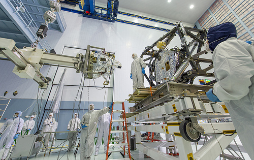
The MIRI itself weighs 181 pounds (82 kg) and is being held by a special balance beam (on the left of the photo), which is getting maneuvered utilizing a precision overhead crane by the engineer at the base of the ladder.

Photo Credit: NASA/Chris Gunn Text Credit: NASA/Laura Betz

—-

Engineers worked meticulously to implant the James Webb Space Telescope’s Mid-Infrared Instrument into the ISIM, or Integrated Science Instrument Module, in the cleanroom at NASA’s Goddard Space Flight Center in Greenbelt, Md. As the successor to NASA’s Hubble Space Telescope, the Webb telescope will be the most effective space telescope ever built. It will observe the most distant objects in the universe, offer images of the first galaxies formed and see unexplored planets around distant stars.

For far more details, visit: www.jwst.nasa.gov

NASA image use policy.

NASA Goddard Space Flight Center enables NASA’s mission by way of four scientific endeavors: Earth Science, Heliophysics, Solar Program Exploration, and Astrophysics. Goddard plays a leading part in NASA’s accomplishments by contributing compelling scientific information to advance the Agency’s mission.

Follow us on Twitter

Like us on Facebook

Uncover us on Instagram

Good Precision Engineering photos

Good Precision Engineering photos

A couple of good precision engineering images I located:

Reckless precision.
precision engineering
Image by digitalpimp.
Raffles Spot, Singapore

Explore #54, January 18, 2011

SMC Pentax M Zoom 75-150mm 1:4
precision engineering
Image by Yumi Abe
&quotWhat a strange lens !

Mechanically it is a piece of really clever engineering. It is a push-pull zoom, but the lens does not truly extend at all more than its focal range. In common with most of the M series lenses it is beautifully built, exuding solidity and precision. The aperture ring has precise half stop detents. Subsequent comes the wide zoom/concentrate ring. This is uncommon in that 150mm is set with the ring nearest to the camera finish. The zoom/focus is nicely damped, just stiff enough to decrease any zoom creep. The front of the lens extends slightly at short concentrate distance and rotates when focusing. A short built-in sliding hood completes the design and style.

The general look and really feel is of a really heavy, ‘long and thin’ telephoto lens. It is truly not that extended, about the identical length as the DA50-200. The concentrate travel angle is fairly brief at about 120 degrees or much less, just a bit also short for actually precise focusing. Similarly, the aperture clicks are fairly closely spaced. The zoom travel is also brief, at about 2 cm. However, in use it handles well, greater than some other push-pull zooms of that era.

On APS sensor camera it is optically sharp even at f4 over most of the focal variety and becomes quite sharp when stopped down a couple of clicks. There is no geometric distortion to speak of and really small chromatic aberration. There can be just a touch of purple fringing in higher contrast areas. Bokeh is not negative, possibly slightly on the ‘busy’ side – the aperture has only six blades. All round contrast is affordable, contemplating that there are 12 glass elements in the way. Colour is slightly on the cool side.

In its day, on a full frame camera, it would have been a fine portrait zoom lens.

There is however anything not quite appropriate with this lens when employed on a DSLR, such as my K-7. Somehow the shots lack ‘bite’, requiring a fair bit of post-processing contrast tweaking. It is hard to tell whether it is a lack of microcontrast, flare, shortage of pixie dust or some thing else. I suspect that there is just as well considerably glass in the way.

Well, obtaining taken it out on a sunny day with plenty of contrasty light, I have changed my opinion of this lens. It is really extremely sharp and it appears to like a lot of harsh light – as long as you do not let it shine on the front element. Shoot from the shade into the sunlight and it genuinely starts to execute, as it the last 3 shots under.

Becoming an all-manual lens the aperture and focal length are not recorded. The shots beneath were taken largely at f4 (or possibly f5.6) and ‘various’ focal lengths.&quot

supply: www.pentaxforums.com/lensreviews/SMC-Pentax-M-75-150mm-F4…