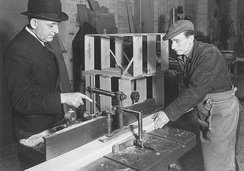
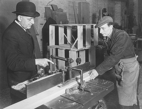
Nice Higher Precision Engineering photographs

Nice Higher Precision Engineering photographs

A handful of nice high precision engineering photos I identified:

Image from page 240 of “The Bell System technical journal” (1922)
high precision engineering
Image by Net Archive Book Photos
Identifier: bellsystemtechni16amerrich
Title: The Bell Program technical journal
Year: 1922 (1920s)
Authors: American Telephone and Telegraph Company
Subjects: Telecommunication Electric engineering Communication Electronics Science Technologies
Publisher: [Quick Hills, N.J., and so on., American Phone and Telegraph Co.]
Contributing Library: Prelinger Library
Digitizing Sponsor: World wide web Archive

View Book Web page: Book Viewer
About This Book: Catalog Entry
View All Images: All Pictures From Book

Click here to view book on the web to see this illustration in context in a browseable online version of this book.

Text Appearing Just before Image:
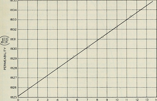
an addi-tional 60-turn winding was used for checking the measurements in thelow-frequency variety. In either case the inductance was low enoughto depress any effect of distributed capacitance far below the precisionof the measurements. Measurements have been produced on a ten-ohm equal ratio arm inductance MAGNETIC LOSSES AT LOW FLUX DENSITIES 217 comparison bridge,^ and were verified at low frequencies employing a 1-ohmratio arm bridge. Calibration of the bridge and common coils wasefifected by creating measurements over the whole frequency range on acalibrated higher good quality air core coil substituted for the test coil. Themaximum correction essential on this account was about .1per cent of the resistance due to the magnetic core. The supply of alternating present was an oscillator-amplifier supply-ing approximately .four watt undistorted energy, calibrated for thesemeasurements against the Laboratories standard frequency. Thecurrent was adjusted by the insertion of resistance in series with the

Text Appearing Following Image:
5 6 7 eight 9 H IN OERSTEADS X ten^ Fig. 2—Core permeability as measured by the ballistic galvanometer. main of the bridge input transformer, and was measured by meansof a thermocouple amongst the transformer secondary and the bridge.The bridge unbalance was amplified by signifies of an impedancecoupled amplifier for the 10-ohm bridge, and by indicates of a resistancecoupled amplifier for the 1-ohm bridge. The amplified unbalance wasobserved by means of head phones at frequencies above 200 cycles, andby means of a vibration galvanometer at lower frequencies. The d.-c.balance required bridge current of about 3 m.a. in the test coil winding,and had the identical precision as the a.-c. balance, viz., db .0002 ohm.The inductance readings had been corrected for the air space within thewinding, and had a relative accuracy of about .03 per cent, and anabsolute accuracy of around .1 per cent. 218 BELL Method TECHNICAL JOURNAL D.-C. Final results The permeability n = BmjHm of the specimen is shown as a enjoyable

Note About Images
Please note that these images are extracted from scanned web page photos that might have been digitally enhanced for readability – coloration and appearance of these illustrations may possibly not perfectly resemble the original operate.

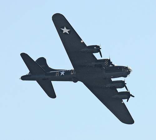
Boeing B-17 – Duxford Airshow Oct 2010
high precision engineering
Image by Feggy Art
Boeing B-17 at Duxford Airshow October 2010.

The Boeing B-17 Flying Fortress was a four-engine heavy bomber aircraft developed in the 1930s for the United States Army Air Corps (USAAC). Competing against Douglas and Martin for a contract to develop 200 bombers, the Boeing entry outperformed each competitors and a lot more than met the Air Corps’ expectations. Though Boeing lost the contract because the prototype crashed, the Air Corps was so impressed with Boeing’s style that they ordered 13 much more B-17s for additional evaluation. From its introduction in 1938, the B-17 Flying Fortress evolved through numerous style advances.

The B-17 was primarily employed by the United States Army Air Forces (USAAF) in the daylight precision strategic bombing campaign of Planet War II against German industrial and military targets. The United States Eighth Air Force primarily based at Thorpe Abbotts airfield in England and the Fifteenth Air Force primarily based in Italy complemented the RAF Bomber Command’s evening time area bombing in Operation Pointblank to assist safe air superiority more than the cities, factories and battlefields of Western Europe in preparation for Operation Overlord. The B-17 also participated to a lesser extent in the War in the Pacific exactly where it carried out raids against Japanese shipping and airfields.

From its pre-war inception, the USAAC (later USAAF) touted the aircraft as a strategic weapon it was a potent, high-flying, extended-variety bomber that was capable to defend itself, and to return house despite comprehensive battle harm. It rapidly took on mythic proportions, and widely circulated stories and photographs of B-17s surviving battle damage increased its iconic status. With a service ceiling higher than any of its Allied contemporaries, the B-17 established itself as an effective weapons system, dropping more bombs than any other U.S. aircraft in Planet War II. Of the 1.5 million metric tons of bombs dropped on Germany by U.S. aircraft, 640,000 tons had been dropped from B-17s.

Common characteristics

•Crew: 10: Pilot, co-pilot, navigator, bombardier/nose gunner, flight engineer-best turret gunner, radio operator, waist gunners (2), ball turret gunner, tail gunner
•Length: 74 ft four in (22.66 m)
•Wingspan: 103 ft 9 in (31.62 m)
•Height: 19 ft 1 in (5.82 m)
•Wing area: 1,420 sq ft (131.92 m2)
•Airfoil: NACA 0018 / NACA 0010
•Aspect ratio: 7.57
•Empty weight: 36,135 lb (16,391 kg)
•Loaded weight: 54,000 lb (24,500 kg)
•Max takeoff weight: 65,500 lb (29,700 kg)
•Powerplant: 4× Wright R-1820-97 Cyclone turbo supercharged radial engines, 1,200 hp (895 kW) each and every

Overall performance

•Maximum speed: 287 mph (249 kn, 462 km/h)
•Cruise speed: 182 mph (158 kn, 293 km/h)
•Range: 2,000 mi (1,738 nmi, 3,219 km) with two,700 kg (six,000 lb) bombload
•Service ceiling: 35,600 ft (ten,850 m)
•Rate of climb: 900 ft/min (four.six m/s)
•Wing loading: 38. lb/sq ft (185.7 kg/m2)
•Power/mass: .089 hp/lb (150 W/kg)

Armament

•Guns: 13 × .50 in (12.7 mm) M2 Browning machine guns in 4 turrets in dorsal, ventral, nose and tail, 2 in waist positions, two beside cockpit and 1 in the reduce dorsal position
•Bombs:
•Short range missions (&lt400 mi): 8,000 lb (three,600 kg)
•Long variety missions (≈800 mi): four,500 lb (two,000 kg)
•Overload: 17,600 lb (7,800 kg)

Text and specifications based on Wikipedia write-up below the Inventive Commons License for non-profit use.

This is the Boeing B17G-105-VE Flying Fortress 124485 G-BEDF (Memphis Belle)

Cool Prototype Engineering images

Cool Prototype Engineering images

Check out these prototype engineering pictures:

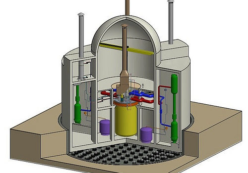
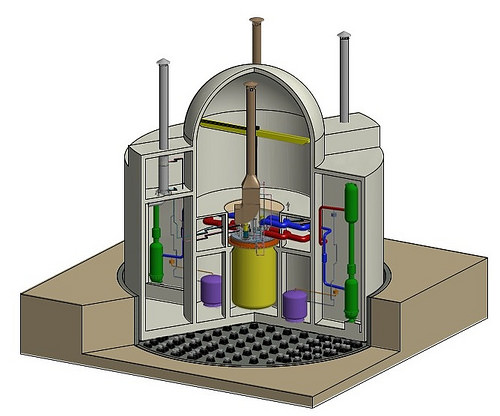
Argonne, KAERI to develop prototype nuclear reactor
prototype engineering
Image by Argonne National Laboratory
Argonne will support the Korean Atomic Power Investigation Institute’s development of a Prototype Generation-IV Sodium-cooled Quick Reactor that incorporates an innovative metal fuel developed at Argonne. The fuel’s inherent safety prospective was demonstrated in landmark tests performed on the Experimental Breeder Reactor-II. Image credit: KAERI. Study a lot more &raquo

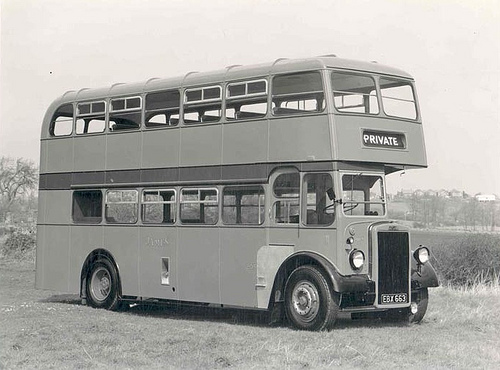
1955 Leyland Bus, Longwell Green Coach Works
prototype engineering
Image by brizzle born and bred
1955 Leyland Double Decker Bus at Longwell Green Coach Operates BS30.

W.J. Bence &amp Sons – Pioneer’s of Early Motor Transport.

New Book About Bristol’s buses

When the very first double-decker buses left the factory and took to the roads, they encountered a key problem – they have been just too high to get under most railway bridges.

One particular answer, perhaps the most obvious, was to reduced the ceiling on the upper deck.

But even though the engineers managed to minimize the height by about a foot or so, the bench-sort seating arrangements upstairs and encroachment into the reduce deck proved unworkable.

There just wasn’t sufficient space for the passengers to sit comfortably.

The Bristol Tramways and Carriage Firm, then primarily based in Brislington, toiled for several years to overcome the problem.

As an alternative of hunting at the upper deck, engineers thought about lowering the chassis and, in 1949, the first of two prototypes took to the road.

The bus, a wonderful example of Bristol engineering and design, was recognized as the Bristol Lodekka.

With an general height of about 13ft 6in, a drop-centre design and style rear axle permitted a a lot lower floor on the bottom deck and a conventional layout on the best deck.

Production started in 1954 and the Lodekka quickly became a staple of the bus scene. Organizations across the UK had been quickly snapping them up.

A single man who remembers the vehicle with fantastic fondness is Brislington-born author and bus enthusiast Martin Curtis.

He told Bristol Times: &quotMy father, Don, worked on the really initial prototype at Brislington’s Motor Constructional Performs. I was a bus enthusiast even prior to I started operating for the old Bristol Omnibus Firm in 1972.

&quotAnd because 1999, I’ve been managing director of the Bath Bus Business.&quot

His book about the Lodekka – the sixth he has researched and written – covers the history, design, improvement and production of the car.

Packed with hundreds of illustrations, it includes chapters on prototypes and trials, pre-production models and then, lastly, how the Lodekka fared following the introduction of one particular- man-operated buses.

Martin, 53, mentioned: &quotIt took me about a year to place collectively, with the photographs coming from a network of friends.&quot

Though the bus chassis was built in Bristol, Martin recalls how the automobiles were then driven to Lowestoft in East Anglia to have the bodywork fitted.

He said: &quotThe 265-mile trip took two days, and it certainly showed the autos were reputable and road-worthy.

&quotLike all the residents of Brislington, I was familiar with the sight of Lodekkas running around on test.

&quotLots of people will bear in mind seeing them driven by way of Bristol’s streets minus their bodywork.

&quotIt was a single of the most revolutionary double- decker designs ever observed.&quot

Martin’s book is the 1st to cover the history of the Lodekka in depth.

He explains: &quotBristol genuinely did lead the way when it came to lowering the entire height of the bus. Other producers tried, but failed.

&quotOver the subsequent three or 4 years, new legislation will imply all buses have to have low floors for simpler access.

&quotYet, here in Bristol, 60 years ago, they had been already pioneering low-floor autos.&quot

But as 1-man operated buses came onto the market place in the 1960s, so the writing was on the wall for the two-man (driver and conductor) Lodekka.

Then, rather unexpectedly, the bus was immortalised in well-liked British culture by the 1970s comedy series, On The Buses starring Reg Varney, which featured the vehicle.

Following their retirement from service, many of the buses survived by becoming converted into open-leading autos for seaside or city tour operate.

Martin said: &quotI seem to have tapped into the nostalgia marketplace.

&quotAll my bus books have sold really nicely – the publishers are fairly surprised.&quot

● Bristol Lodekka, by Martin S Curtis is published by Ian Allan. It fees £16.99.

Bookbinding Miniature Book. In Progress. | Catherine Mommsen Scott
prototype engineering
Image by Doeki
2.five&quot x 3.5&quot
Prototype, reverse engineered from one of my initial books. Lost all my patterns in moving.
Faux leather cover with gold antiquing. Plain brown paper pages. Hand sewn, seven signatures of 5 sheets each.
Headband is mulberry paper and cord.

Cool Precision Engineering Organizations photos

Cool Precision Engineering Organizations photos

Check out these precision engineering businesses images:

Image from page 149 of “Railway and locomotive engineering : a sensible journal of railway motive power and rolling stock” (1901)
precision engineering companies
Image by World wide web Archive Book Images
Identifier: railwaylocomotiv24newy
Title: Railway and locomotive engineering : a practical journal of railway motive energy and rolling stock
Year: 1901 (1900s)
Authors:
Subjects: Railroads Locomotives
Publisher: New York : A. Sinclair Co
Contributing Library: Carnegie Library of Pittsburgh
Digitizing Sponsor: Lyrasis Members and Sloan Foundation

View Book Web page: Book Viewer
About This Book: Catalog Entry
View All Pictures: All Pictures From Book

Click here to view book on the internet to see this illustration in context in a browseable on the web version of this book.

Text Appearing Ahead of Image:
-jected to all manner of importunities toside-step or distort details already stated. A night train was descending the gradeinto a division station where a change ofengines was to be produced. As the trainapproached the station it was not underfull manage and the engineer, evidently infear of striking the engine waiting to re-lieve him, jumped off and was killed. Thesuit was promptly instituted against thetailroad organization and long soon after, I withnumerous other people, were notified to appearat the court property of a fairly tiny In-diana city, on a specific date. The courtconvened in due time, a jury was drawnand soon after a number of preliminaries,among which was a supply of cuspidorsfor the granger jurymen, all of whomwere vigorously chewing plug tobacco, andoccasionally expectorating at the nearestcuspidor with practically the precision of aprojectile fired from a gun, the trial started.For some purpose not apparent I was re-tained as the final witness and as a conse-quence I sat for numerous days in the court

Text Appearing Right after Image:
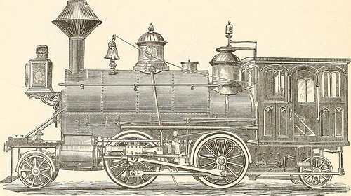
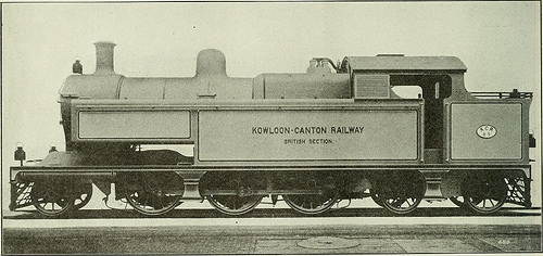
TANK LOCOMOTIVE FOR THE KOWLOON-CANTON RAILW each and every. The passenger coaches are of thebogie type, with corridor, and fittedthroughout with electric light and allmodern improvements. There are alto-gether eight passenger coaches. Thecompletion of this line will no doubtprove to be of fantastic value to Britishand other interests in China. These factsshow also the little beginnings fromwhich railway enterprises frequently commence.China is awakening, and in a couple of yearsit is probable that the complete country willbe covered with the modern steel higher-methods of commerce. Old-Time Railroad Reminiscences.By S. J. Kidder. I believe a somewhat general impressionprevails among the railroad laymen thata man who gets into the air brake busi-ness has his time fairly completely occupied inlooking soon after such issues as pertain to I have been named upon fairly a numbercf occasions to seem as a witness on behalfof railroads, but thankfully was in a position toget off with but slight cross-examinationby resorting to some of the intr

Note About Photos
Please note that these images are extracted from scanned page photos that may have been digitally enhanced for readability – coloration and look of these illustrations might not completely resemble the original work.

Leica X1 Assessment
precision engineering companies
Image by elviskennedy
For the full set of Leica X1 sample photos go to the Leica X1 Sample Images set in the elviskennedy photostream right here www.flickr.com/pictures/elviskennedy/sets/72157626825279684…

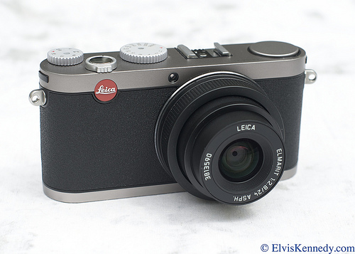
The Leica X1 appears and feels like the precision instrument that you would count on it to be. It is a Leica after all. For more than one hundred years Leica has engineered and crafted state-of-the-art optical instruments, and the Leica X1 is no exception – it continues the tradition.

What is the Leica X1? Simply place it is a big sensor, tiny body digital camera. By massive sensor Elvis means significantly bigger than the sensors found in pocket sized point and shoot cameras. In fact, the sensor in the X1 is almost as big as the sensors discovered in digital SLR cameras. Bigger sensor generally indicates higher image quality (a lot more on that in a moment). By tiny physique Elvis indicates significantly smaller than digital SLR cameras. Smaller body indicates less difficult to carry and have with you (and less difficult to hide for you secret agent types).

What does all of this imply? Essentially it implies that you can have image quality nearly as high as an SLR camera in a package almost as small as a point and shoot camera. These are both quite good issues.

You can note that the Leica X1 is not a do everything camera and be disappointed. It does not have lots of menus filled with shooting choices, post processing choices or an array of fancy shooting gimmicks and tricks. It doesn’t have (gasp!) video. You happen to be stuck with a 35mm field of view lens. Or you can take the alternative view as Elvis does and look at the Leica X1 as a do a single thing really properly camera and be happy.

The Leica X1 is basic to operate. You won’t miss shots since you left your menu settings on some silly choice. You won’t waste time more than-considering which shooting alternative or which lens to use. You won’t be disappointed with the shaky video that you get with most SLR cameras. You will be amazed at the image quality. And you are going to be tickled with the famous Leica &quotlook&quot that you can only get with genuine Leica lenses.

Leading 5 Factors to Really like the Leica X1

The Leica lens and the Leica lens &quotlook&quot
It compliments your digital SLR
Ease of use
Image Good quality
Image High quality

NOTE: Elvis’ testimonials are based on gear that Elvis bought with his own, challenging-earned income. This means that Elvis went via some sort of justification in acquiring the piece of gear and/or that it was probably to fill some want. Elvis does not acquire stuff just to assessment it. Consequently, if you’re searching for reasons not to like the Leica X1 you will want to look elsewhere. Elvis is a lover, not a hater. The intent of this review is to show you what the X1 can and can not do, how it operates in actual operation and what you can count on in end benefits. The intent is not to nit pick the X1 or to evaluate it to a variety of other cameras in some sort of contest.

The Leica Lens &amp The Leica &quotLook&quot

The Leica lens integrated with every single X1 is a valid purpose to obtain the X1. It really is a 24mm f/two.eight Elmarit. Leica aficionados recognize that to be a globe class lens. To these new to Leica, let Elvis to assure you that the lens top quality is of the highest order. The &quotlook&quot of a lens, or household of lenses is difficult to describe. Ineffable, really. It will not quit Elvis from trying though. Elvis’ two favorite lenses ever are the Leica 35 f/two Summicron aspherical and the Nikon 85 f/1.4. These two lenses are bright, sharp, have a remarkable flatness of field and when used appropriately make quite pleasing out of concentrate ( bokeh ) places. These attributes make for great landscapes and spectacular portraits. Elvis argues that these two lenses are so very good that you can justify acquiring a great camera physique on which to attach them. They really are that good.

What does that have to do with the lens on the X1? The 24mm on the X1 produces photographs that give a &quotlook&quot that is comparable to Elvis’ two favored lenses described above. Vibrant, sharp, flat field and pleasing out-of-concentrate places. And do not let the 24mm moniker concern you. As an APS-C sensor camera there is a multiplication aspect to consider: 1.five. That 24mm on the X1 offers you a 35mm field of view, which is just about the most versatile field of view there is.

Take a close appear at the sample pictures provided by Elvis. Click on every single image to view the photos in their full-file glory. And click on More Pictures to see, well, Far more Photos.

It Compliments Your Digital SLR

The X1 is the ideal (and Elvis means ideal) camera with which to compliment your digital SLR. Your SLR gives you lots of shooting possibilities, lots of lens choices, video and all types of fun tricks to play around with. That is your principal camera. The Leica X1 compliments this by getting tiny and pocketable with higher image high quality. Going on trip? Use your SLR at Disney Globe, on the vehicle trip to the mountaintop lookout and on photography certain excursions. Pack the X1 for street shooting, at the beach, hiking and when out to dinner. Shooting a sporting occasion? The SLR is excellent for action shots throughout the game. The X1 is great for shooting the group for the duration of pre-game pep talks, players on the sidelines and right after game celebrations and group activities. Weddings? SLR is fantastic for formals and receptions. Leica X1 is great for in the course of the ceremony given that it is silent in operation. You get the notion. With an SLR and an X1 you are well equipped for any photographic opportunity.

Ease of Use

In use the Leica X1 is terrific. Take a couple of minutes to recognize the few shooting possibilities that the X1 provides, set your favorites and you are now prepared to shoot at a moment’s notice. There is absolutely nothing to the X1 that will slow you down. It really is a photographic machine – plain and easy.

Is it the quickest focusing camera ever? No it is not. In dim light it can take a handful of seconds to focus. But keep in mind that the Leica lens is sharp and what you want is precise focusing to take benefit of that sharp lens. Just like a manually focused lens it can take a moment to get it critically right. And in medium to vibrant light it’s quickly. (See Elvis’ test of the enhanced focusing speed with new firmware Right here).

The battery and charger are both little and portable. The SD cards employed in the X1 are universally accepted, fast and durable (and low-cost). The DNG files can be opened with virtually any photo editing application and are claimed to be future-proof.

The little size and light weight of the Leica X1 can’t be overstated. The camera is extremely effortless to deal with, use and pocket. But don’t let the size and weight fool you – it is built to exacting standards and is jewel-like and elegant to hold.

It may quite nicely be the camera with the highest image high quality that you could hand to a stranger to take your image in front of (name landmark right here) and not need to explain to the stranger how to use it. It’s simplicity belies it’s strength.

Image Quality

If you are familiar with Leica imaging you will instantly recognize that pedigree in the X1 photographs. If you are new to Leica you are in for a treat. The X1, like the Leica M series of cameras and lenses, produces sparkling, clear and crisp photographs with smooth and pleasing out of concentrate locations. Lack of flare and lack of field curvature are other traits in the planet of Leica.

You needn’t appear hard to discern Leica photographs. It really is instantly apparent. Elvis is particularly fond of the crispness of Leica photographs. It really is not specifically sharpness and it’s not specifically contrast – it is crispness (Elvis warned you at the outset of this evaluation that these are difficult issues to define). Just appear at the samples and see if you can note these factors.

Point and shoot cameras and four/3rds cameras are no match for the Leica X1 when it comes to image quality. Some DSLRs can have a slight edge but at a size and weight expense. The Fuji X100 is a close match in a distinct (not as basic) physique, and should be a camera that you consider (see Elvis’ comparison of the Leica X1 and Fuji X100 Here), but it won’t give you the Leica &quotlook&quot, ease of use or pocket ability.

When it comes to image quality, engineering matters. Leica excels at engineering. Some primary keys are sensor high quality, lens (glass, not plastic) quality, lens-to-sensor distance, lens element positioning and consistency, lens element coatings, use of aspherical surfaces, durability of supplies used. All of these regions are strengths of the Leica firm and have been for generations.

Superior lens glass is more critical than a high resolution image monitor. A superior sensor is much more important than a video mode. A clean and straightforward but very technical light path is far more critical than page after web page of shooting and post processing possibilities. You get the idea right here. Leica focused on the image path and little else.

A larger image sensor is a extremely very good issue. All things being equal, a bigger sensor captures images with a greater dynamic range than a smaller sized sensor. Basically, greater dynamic range signifies much more detail in dark places, medium locations and light locations of the scene. Greater image quality. As a bonus, bigger image sensors generate a smaller depth of field for any given aperture setting, allowing for superior out of focus regions and image &quotpop&quot.

Leica managed to mount a big image sensor into a little camera and for the initial time we have a pocketable camera that can generate higher image quality. Some believed that the so-called 4 thirds method cameras were going to be the resolution. The sensor in the Leica X1 is roughly 60% larger than the four thirds sensors and in Elvis’ estimation the resulting image top quality is at least double. There’s practically nothing incorrect with the 4 thirds cameras but the X1 image top quality is greater. The image sensor in the X1 is eight to ten instances larger than the sensors in common point and shoot cameras. You don’t require Elvis to do that math for you.

In a planet of do-it-all cameras with choices as well numerous to mention (let alone completely understand) one particular could say that Leica took a flyer with the X1. Ignoring video, not getting tempted with gimmicks and gadgets could be considered a threat. But that would be a full misunderstanding of what Leica is. Leica has often been about stripping photography down to it really is bare essence. Focus on the image. Let other companies throw out dozens of possibilities to see what sticks. Leica must be applauded for putting a superior, big sensor behind a true Leica lens and stuffing each into an elegant and portable body.

For a complete set of sample photos taken with the Leica X1 got to Elvis Kennedy’s Leica X1 group folder of the photostream. The outcome of all of this engineering is that you can get a high image quality creating machine in a modest and elegant package. A correct industry top item, the Leica X1.

For the complete set of sample photographs go Right here, and be certain to hit the &quotO&quot button above every single image to see them in their Original, complete size.

For far more go to www.elviskennedy.com

Douglas A-3 Skywarrior simulator cab:
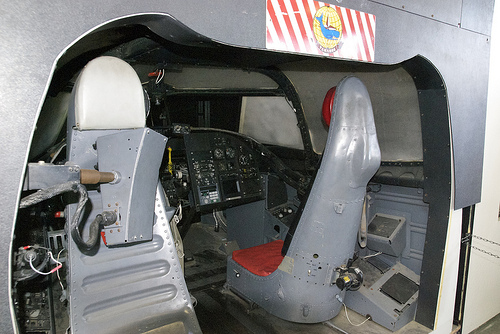
precision engineering companies
Image by wbaiv
Note VAK-308 sticker
This simulator has ‘stuff’ for the pilot and the bombardier-navigator/refueling/electronic warfare wizard. No co-pilot in an A-3. The stuff in front of the proper seat would have been bombing and navigation equipment, initially. From my check out to the actual EKA-3B outside, I do not think this is the same appropriate-seat stuff as that a tanker. Could be earlier, later, some of each, for an ECM bird. The pilot and rear gunner sat back to back in the single, fore-and-aft-facing seat, on the left, which has no actual aft-facing seat in this image. There is some kind of an electronics box in the way….

The Navy insisted on the radar guided twin 20mm tail turret, which Heinimann &amp the Douglas engineers believed was unnecessary weight… but the turrets came off early and the squared-off fuselage endings contained who knew what neat radio antennae. And other stuff. A massive, capable aircraft, the A-3 was bought as a nuclear bomber, speedily discovered a second career as a tanker and added all sorts of electronic reconnaissance and electronic warfare capability in addition to hauling fuel for those who necessary it. For the very first time, over Vietnam and points east, airplanes with heretofore fatal fuel leaks from enemy fire could plug into a tanker and burn sufficient of the fuel pouring by way of them to fly property, Or close to property. Away from the shore.

As was distressingly widespread in the 1960s, when the Navy’s plane was put up against what the USAF had been buying, the Navy plane was much better. That’s how the USAF got the F-four Phantom II (quite briefly the F-110) and the A-7 (constantly the A-7). Neither the USAF nor Douglas could stop the gravitational drift that overwhelmed the &quotUSAF A-3&quot, which morphed into the Douglas B-66 Destroyer. Bet they cost a lot much more than an A-three. (a person have to have giggled more than that name…) No surprise, the USAF already had big tankers, so the B-66s became electronic warfare platforms in rapid time… over Vietnam, over Germany, and anywhere else the USAF flew in the 1960s.

You can locate images of a formation of F-105D &quotThunderchiefs&quot all dropping their iron bombs at the identical time, on signal from an RB-66, that presumably has a radar bombing set-up, and/or unique radio navigation aids. Because the bombs are being dropped through 10/10th cloud. Not, mmm, &quotprecision&quot weapon delivery, if you will. Several planes dropping numerous bombs and quite possibly in numerous attacks to take out a single target… say, the Paul Daumer Bridge or &quotHanoi Thermal Power Station&quot.

Its good to feel you could precompute almost everything and drop iron bombs from four-7 miles up and have a military impact. A lot of folks DID think that, but it wasn’t one thing that actually occurred. Unless you could drop hundreds of bombs from your three plane cells of B-52s. Finally, with Paveway laser-guided bombs, the USAF got precision weapons that really worked. Much more than a single target per plane, rather of a lot more than a single plane, more than one particular raid, per target.

Which is why the US Navy and Marine Corps aviators had place so much effort into hitting certain targets bang proper on the head using dive bombing. For instance, in Nicaragua, in the 1920s and 30s. And other ‘close air support’ strategies.

DSC_0135
Father’s day, 2013
Cool Precision Engineering pictures

Cool Precision Engineering pictures

Some cool precision engineering photos:

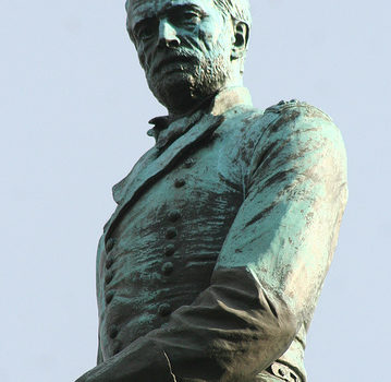
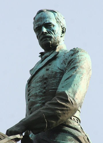
William T. Sherman
precision engineering
Image by dbking
William Tecumseh Sherman Monument
Place: 15th Street at Pennsylvania Ave. NW
Sculptor: Carl Rohl-Smith
Date: 1903
Medium: Bronze

Even though the Grant Memorial might be the grandest, the Sherman Monument behind the U.S. Treasury is the biggest and most complex of all the Civil War memorials.

Before the Civil War, Sherman had floundered in life. He graduated from West Point in 1840 and went on to serve in the Mexican War, but resigned his commission in 1853 to enter the banking organization. But as banks failed, so did his banking career. When he tried to return to the military he was rebuffed and turned to law but lost the only case he tried. In 1861, at the outbreak of the Civil War, Sherman was serving as superintendent of a new military college in Louisiana but turned down a commission in the Confederate Army. At age 41, he was reappointed as colonel of the 13th infantry as the standard U.S. army expanded. His memoirs note that he “felt as though there was now a goal in his life” at this commission. Attaining the rank of commander of the Army of the Tennessee in 1863, Sherman’s “March to the Sea” during the winter of 1864-1865 captured the imagination of the North. This occasion led the press, who Sherman mistrusted and who disliked him in return, to turn into an immensely attractive hero. As a lieutenant general and then common and commander of the whole army from 1869-1883, Sherman was well-liked amongst veterans, whose welfare he looked after. He was active in veterans’ organizations, in continual demand as a speaker at reunions, dedications, and encampments, and he rarely turned down an invitation to “mix with the boys.” When word of his death in February 1891 reached the Society of the Army of the Tennessee, its officers began to program for a memorial honoring his memory.

Choice of the Sculptor

As with the Grant Memorial (although many years later), members at the society’s summer season encampment voted to erect a memorial to honor him “in the nation’s capitol, the heart of Union he had fought to save.” Congress was asked for and appropriated ,000 to establish the Sherman Monument Commission. The Society swiftly established committees in each and every state to raise funds, writing solicitation letters to many military organizations of the day, as well as encouraging each and every Union veteran to contribute to the statue fund “so that when the statue is erected in Washington, every soldier who sees it will really feel that it is a component of his effort.” With the plea for funds was an emotional circular to remind veterans of Sherman’s concern for them. Regardless of the appeals, only ,469.91 was raised, requiring Congress to double its contribution. By 1895, confident that they would be effective in raising the final funds required, the Society announced a competitors to pick a design for the monument. The Society wanted only equestrian models from American artists and asked the National Sculpture Society to assist in the choice of the artist.

By April 1896, twenty-3 sculptors had submitted models. Numerous of the sculptors had submitted models for earlier monumental commissions but had lost. The models had been displayed in the basement of the War Division where the public could view them and offer opinions. In mid-May possibly, the commission announced 4 finalists and the National Sculpture Society sent a delegation of the nation’s most prominent sculptors to evaluate the finalist’s models. The public had favored the most elaborate model, submitted by Danish born Carl Rohl-Smith, but the National Sculpture Society’s judges relegated Rohl-Smith’s design and style to the bottom, discovering “it is ill conceived and overdone.” Two weeks following the National Sculpture Society’s delegation opined, the Sherman Monument commission announced Rohl-Smith as the winner. The losers had been outraged and cried foul, claiming that the Sherman Monument Commission entirely disregarded the opinion of the professionals. The National Sculpture Society also protested the decision. The “Washington Star” newspaper referred to as the competitors a “bunko game.” In June, at the urging of the National Sculpture Society, Sen. Wolcott (CO), who had mentioned the nation’s capital was already disgraced by sufficient bad sculpture, presented a resolution for an inquiry into the award of the Sherman commission. What ensued was a debate that intensified the fantastic divide amongst the “artistic experts” who disliked Rohl-Smith’s model and the public’s wish for Rohl-Smith’s design and style. The wrangling continued till July, with Rohl-Smith possessing to deny that he had any influence in Washington, only the ideal design and style. Finally, the opposition surrendered and Rohl-Smith went to work on his sculpture.

The Location

Whilst the selection approach was contentious at greatest, the selection of the location for Rohl-Smith’s statue, which was going on simultaneously, was much less difficult. A slight incline on the south side of the Treasury building was identified, because it was exactly where Sherman had watched the two-day Grand Review of the Union Army in Might 1865. On the initial day of the evaluation, Sherman stood silently watching the Army of the Potomac march by in precision. Sherman’s personal men (the Army of the Tennessee) would pass in assessment the second day, and worried they would not measure up to the Army of the Potomac, he rode across the river to their camp and called collectively all his commanding officers. He described in detail the precision marching of the Army of the Potomac, hoping that the officers would relay this to his men and inspire them to appear as sharp as the Army of the Potomac. On the second day of the review, Sherman led the Army of the Tennessee up Pennsylvania Avenue with the military bands playing “Marching Via Georgia,” a new tune in their honor. As he and his band of males neared the rise at the Treasury creating, Sherman pulled aside, turned facing eastward in his saddle, and with President Johnson and other dignitaries watched his guys march down Pennsylvania Avenue toward him and the reviewing dignitaries.
Commenting on the second day of the Grand Overview, the Washington Star reported that “this day’s guys were taller, lankier, more sun beaten that these who had marched the day before. Their strides have been longer, more confident. They swung along with an easy grace and their spirits high. They were magnificent.” Crowds along Pennsylvania Avenue cheered them, throwing flowers and Sherman was practically overcome with emotion. In his memoirs he recalls this to be “one of the happiest, most satisfying moments of his life.” For that reason, this spot was chosen as the place for the Sherman monument, and the pride Sherman felt watching his males would be captured by Rohl-Smith in the statue itself.

The Sculpture Requires Shape

In 1897, Rohl-Smith set up his studio in a huge barn-like structure that the Secretary of the Treasury built for him near the web site. The developing integrated an apartment exactly where he and his wife Sara lived even though he worked. In 1900, having completed models for the equestrian statue and 3 of the 4 soldiers that would stand guard at the monument’s corners, Rohl-Smith sailed to Denmark for a visit. While there, he died unexpectedly at age of 52 in Copenhagen. His wife, Sara, asked the Sherman Monument Commission to permit her to arrange the artist who would complete the statue and the commission agreed. Sara, along with some of the young Scandinavians who had been operating with her husband, effectively directed the completion of the monument making use of her late husband’s original drawings. In August 1903, the Washington Star reported that the first cast sections of the 14’ tall equestrian statue have been arriving at the website. Sherman’s torso, hands, arms, shoulders, neck and head comprised the biggest piece.

Design and style Components

On each and every corner of the tiered platform, facing outward, were placed four life size soldiers representing infantry, cavalry, artillery, and engineers. A relief on the north side of the pedestal shows guys marching by means of Georgia as slaves step from their quarters to watch them pass. The relief on the south side depicts the Battle of Atlanta with Sherman and his staff at headquarters as smoke rises from the burning city in the distance. The reliefs on the west and east sides of the pedestal show Sherman walking amongst his males sleeping about a campfire and the basic with his officers on horseback just before the Battle of Missionary Ridge. Pairs of medallions bearing bas-reliefs of Sherman’s army and corps commanders (James Birdseye McPherson and Oliver O Howard, John A Logan and Francis Preston Blair, Greenville M. Dodge and Edward G. Ransom, and Benjamin Grierson and Andrew J. Smith) flank the larger reliefs on the east and west sides. Massive bronze groups installed halfway up the monument’s east and west sides depict “Peace” and “War”. “Peace,” on the east side, depicts a graceful woman holding an olive branch accompanied by 3 children, one particular feeding a dove. “War,” on the west side, is a horrible fury, seething with rage and hatred, who tramples humanity in the form of a dead young soldier at her feet. Big bronze vultures perch on the body about to feast on its flesh, graphically driving property Sherman’s well-known observation that “war is hell.” Inscribed on the north façade is yet another Sherman quote: “war’s genuine object is much more excellent peace.” Ultimately, inscribed in the wide mosaic band about the base of the monument are the several battles in which Sherman participated.

The Dedication Ceremony

The Society of the Army of the Tennessee created the plans for the dedication of the Sherman Monument. They arranged specific excursion trains to bring veterans to Washington, special hotel rates, and activities for veterans’ wives. As the date of dedication arrived, October 15, 1903, thousands arrived in Washington and filled all hotels, forcing numerous to remain in hotels as far away as Baltimore and Annapolis. In Washington, miles of bunting and acres of flags decorated businesses, properties, and government buildings. The base of the monument itself was entwined with 400’ of garland and at each and every corner stood wreaths 7’ in diameter. On every side of the base was a 6’ high shield of red, white, and blue flowers—one for every of the 4 armies. The statue of Sherman was enfolded amongst two huge American flags suspended on wires whilst a lot more flags covered the bronze soldiers at the corners. On the reviewing stand for the parade that preceded the ceremonies Turkish carpets were laid. Overstuffed armchairs for President Theodore Roosevelt and other dignitaries lined the freshly painted railings of the reviewing stand. A lot more than a thousand folding chairs had been arranged in a semi-circle in front for the actual unveiling, with two hundred unique chairs for the “veterans who had left limbs to rot on the battlefield” proper at the base of the statue. Specific tables were set aside for the press and the Western Union operators. The parade, which stretched for miles, started at 2:00pm. President Roosevelt could barely contain his enthusiasm and kept leaping out of his chair to wave and shout to passing units. The last tune played before the ceremony was “Marching By way of Georgia.” General Greenville Dodge, president of the Society of the Army of the Tennessee, presided. At Dodge’s signal, the late general’s young grandson, William Tecumseh Sherman Thorndike, pulled the cord that parted the flags to show Sherman astride his horse.

The ceremony was uncommon among dedications for the eloquence of its speakers. Dedication speeches had previously been patriotic and sentimental, but the speakers at this a single, particularly President Roosevelt, rose above the standard nostalgia. President Roosevelt’s speech was filled with moving, challenging imagery, because Roosevelt had an agenda and he relished the pulpit afforded to at this dedication ceremony (the nation had only lately finished the Spanish-American War), but his words express thoughts still valid these days.

President Roosevelt stated that, as an emerging international power, the nation must be ever vigilant and always robust and veterans in the audience roared in agreement. Roosevelt also used this chance to contact for a powerful national defense, chiding opponents by saying, “No man is warranted in feeling pride in the deeds of the Army and Navy of the previous if he does not back up the Army and Navy of the present.” Roosevelt wanted no 1 to rest on past laurels, calling for Americans to be vigorous, rigorous, up and performing noble deeds, and pursuing lofty objectives, stating that heroes like Sherman ought to spur citizens to comparable acts. The President known as for new patriotism, honesty and vigilance – all qualities exhibited by Sherman and other “great dead.” Roosevelt continued: “The triumphs of the previous need to be lessons that, if learned, would lead to victory in challenges however to come. It is a fantastic and glorious point for a nation to be stirred to present triumph by the splendid triumphs of the previous. But it is a shameful thing for a nation if these memories stir it only to empty boastings…We of the present, if we are correct to the past, must show by our lives that we have learned aright the lessons taught by the males who did the mighty deeds of the previous.” As Roosevelt spoke, the thousands of veterans sitting in front of him, who had carried out the “mighty deeds” of the past, have been stirred to know that this man wasn’t searching back in time but forward. He told these assembled that their hard won victories would guide the nation into a glorious future that they would not reside to see but whose destiny they had guaranteed. Through Roosevelt’s guarantee of a sort of immortality, the males of the armies of the Tennessee, Cumberland, Ohio and the Potomac rose and gave him 1 ovation following one more.

Good Mechanical Engineering China photos

A few nice mechanical engineering china pictures I discovered:

Image from page 318 of “Railway mechanical engineer” (1916)
mechanical engineering china
Image by World wide web Archive Book Photos
Identifier: railwaymechanica96newy
Title: Railway mechanical engineer
Year: 1916 (1910s)
Authors:
Subjects: Railroad engineering Engineering Railroads Railroad automobiles
Publisher: New York, N.Y. : Simmons-Boardman Pub. Co
Contributing Library: Carnegie Library of Pittsburgh
Digitizing Sponsor: Lyrasis Members and Sloan Foundation

View Book Page: Book Viewer
About This Book: Catalog Entry
View All Images: All Images From Book

Click here to view book on the web to see this illustration in context in a browseable on the internet version of this book.

Text Appearing Before Image:
n referred to, the Board of Communication rec-ommended an extension to Suiyuan. This undertakingreceived imjjerial sanction in 1909 and building wascommenced in the following year. The length of the secondsection is 2J5 miles. This, as nicely as all other imi)ortantlines in China, is of the common gage, four ft. XJj in. The line runs along the west wall of Pekin and then ina northwesterly direction to Nankow, passing over the WestHills via Nankow Pass, to Kaigan and thence to Fengchcuand Suiyuan. The principal rail connections are at Fengtaiwith the Pekin-Mukden and Pekin-Hankow lines, .hout7.S per cent of the income received is from freight and thebalance from jiassenger visitors. Tlie heaviest movementsare toward Pekin and Fengtai. Fair grades were obtainedfor tlie line witli the cxcejjtion of the portion more than the WestHills, at which point there is a grade of ,S..S3 per cent,11 miles long with uncom])ensated curves (jf 600 ft. radius.ibis grade ((lUrcIs tlie nidvenuiit nf tr.iffn.

Text Appearing After Image:
Mik.ido Lor.omotlvc U»ctl on Level Section* 305 306 RAILWAY MECHANICAL ENGINEER Vol. 96, No. 6 Table of Dimensions, Weights and Proportions Cylinders, higher pressure 24 in. by 28 in. Cylinders, low pressure 38 in. by 28 in. Valves and valve setting: … , Kind and size, H.P Piston 14 in., single ported Type and size, L.P Piston 16 in., double ported Maximum travel H.P. 6A in., L.P. 6 in. Outside lap HP^ 1 in,, LP- !^ !• ExhLust clearance H.P. ■4 in., L.P. A in. Lead in complete gear H.P. H in., L.P. A in. Weights in worTv-ing order: On drivers ^S?™ r On front truck S^°2 ^ On trailing truck 29.000 b. Total engine 446,000 b. Tender 192.700 lb. Wteel base: Driving, every single engine i j &lt 11 Total engine L c Total engine and tender 85 It. six in. Wheels, diameter outdoors tires: Driving Front and trailing truck Tender Journals, diameter and length: . , ., • Driving, primary 10 .in. by 12 m. Driving, other individuals 9 in. by 12 in. Front and trailing truck 6 in. by 1-i in. Variety ^%Vn lb Steam press

Note About Pictures
Please note that these pictures are extracted from scanned page pictures that may have been digitally enhanced for readability – coloration and look of these illustrations may not completely resemble the original function.

Jianwai SOHO 24
mechanical engineering china
Image by tom$
JIAN WAI SOHO
location: Beijing, China
principal use: several dwelling, shop, workplace, sport club, preschool
site location: 122,775 sq meters
developing location: 34,823 sq meters
total floor region: 504,237 sq meters
structure: reinforced concrete, partly steel frame
quantity of stories: two basements and 31 stories
architects: Riken Yamamoto &amp Field Shop, C+A, MIKAN, Beijing New Era Architectural Design and style, Beijing Dongfang Huatai Architectural &amp Engineering
structural engineers: Plus One Structural Des. &amp Eng. Firm
mechanical engineers: Kankyo Engineering
interior designers / furniture designers: Yasuo Kondo Design
sign designers: Hiromura Design and style Office

Cool Precision Engineering Company photos

Cool Precision Engineering Company photos

Check out these precision engineering business images:

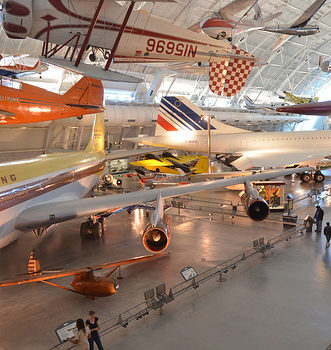
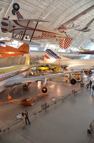
Steven F. Udvar-Hazy Center: south hangar panorama, including Grumman G-22 “Gulfhawk II”, Boeing 367-80 (707) Jet Transport, Air France Concorde amongst other folks
precision engineering company
Image by Chris Devers
Quoting Smithsonian National Air and Space Museum | Grumman G-22 &quotGulfhawk II&quot:

A single of the most exciting aerobatic aircraft of the 1930s and ’40s, the Grumman Gulfhawk II was constructed for retired naval aviator and air show pilot Al Williams. As head of the Gulf Oil Company’s aviation department, Williams flew in military and civilian air shows around the nation, performing precision aerobatics and dive-bombing maneuvers to market military aviation throughout the interwar years.

The sturdy civilian biplane, with its robust aluminum monocoque fuselage and Wright Cyclone engine, practically matched the Grumman F3F regular Navy fighter, which was operational at the time. It took its orange paint scheme from Williams’ Curtiss 1A Gulfhawk, also in the Smithsonian’s collection. Williams personally piloted the Gulfhawk II on its last flight in 1948 to Washington’s National Airport.

Present of Gulf Oil Corporation

Manufacturer:
Grumman Aircraft Engineering Corporation

Date:
1936

Nation of Origin:
United States of America

Dimensions:
Wingspan: 8.7 m (28 ft 7 in)
Length: 7 m (23 ft)
Height: three.1 m (10 ft)
Weight, aerobatic: 1,625 kg (3,583 lb)
Weight, gross: 1,903 kg (4,195 lb)
Leading speed: 467 km/h (290 mph)
Engine: Wright Cyclone R-1820-G1, 1,000 hp

Supplies:
Fuselage: steel tube with aluminum alloy
Wings: aluminum spars and ribs with fabric cover

Physical Description:
NR1050. Aerobatic biplane flown by Significant Alford &quotAl&quot Williams as demonstration aircraft for Gulf Oil Business. Related to Grumman F3F single-seat fighter aircraft flown by the U.S. Navy. Wright Cyclone R-1820-G1 engine, 1000 hp.

• • • • •

Quoting Smithsonian National Air and Space Museum | Boeing 367-80 Jet Transport:

On July 15, 1954, a graceful, swept-winged aircraft, bedecked in brown and yellow paint and powered by four revolutionary new engines first took to the sky above Seattle. Constructed by the Boeing Aircraft Firm, the 367-80, far better known as the Dash 80, would come to revolutionize industrial air transportation when its created version entered service as the well-known Boeing 707, America’s first jet airliner.

In the early 1950s, Boeing had begun to study the possibility of creating a jet-powered military transport and tanker to complement the new generation of Boeing jet bombers getting into service with the U.S. Air Force. When the Air Force showed no interest, Boeing invested million of its personal capital to develop a prototype jet transport in a daring gamble that the airlines and the Air Force would acquire it as soon as the aircraft had flown and verified itself. As Boeing had done with the B-17, it risked the organization on 1 roll of the dice and won.

Boeing engineers had initially based the jet transport on studies of improved styles of the Model 367, better identified to the public as the C-97 piston-engined transport and aerial tanker. By the time Boeing progressed to the 80th iteration, the design and style bore no resemblance to the C-97 but, for security motives, Boeing decided to let the jet project be recognized as the 367-80.

Work proceeded speedily after the formal commence of the project on May 20, 1952. The 367-80 mated a huge cabin based on the dimensions of the C-97 with the 35-degree swept-wing design and style based on the wings of the B-47 and B-52 but considerably stiffer and incorporating a pronounced dihedral. The wings were mounted low on the fuselage and incorporated high-speed and low-speed ailerons as properly as a sophisticated flap and spoiler system. 4 Pratt &amp Whitney JT3 turbojet engines, each producing 10,000 pounds of thrust, had been mounted on struts beneath the wings.

Upon the Dash 80’s first flight on July 15, 1954, (the 34th anniversary of the founding of the Boeing Company) Boeing clearly had a winner. Flying one hundred miles per hour more quickly than the de Havilland Comet and significantly bigger, the new Boeing had a maximum variety of much more than 3,500 miles. As hoped, the Air Force bought 29 examples of the style as a tanker/transport soon after they convinced Boeing to widen the design and style by 12 inches. Satisfied, the Air Force designated it the KC-135A. A total of 732 KC-135s had been constructed.

Speedily Boeing turned its attention to promoting the airline industry on this new jet transport. Clearly the industry was impressed with the capabilities of the prototype 707 but in no way more so than at the Gold Cup hydroplane races held on Lake Washington in Seattle, in August 1955. For the duration of the festivities surrounding this occasion, Boeing had gathered several airline representatives to get pleasure from the competitors and witness a fly previous of the new Dash 80. To the audience’s intense delight and Boeing’s profound shock, test pilot Alvin &quotTex&quot Johnston barrel-rolled the Dash 80 over the lake in full view of thousands of astonished spectators. Johnston vividly displayed the superior strength and functionality of this new jet, readily convincing the airline industry to buy this new airliner.

In searching for a market place, Boeing located a prepared buyer in Pan American Airway’s president Juan Trippe. Trippe had been spending much of his time browsing for a suitable jet airliner to enable his pioneering firm to preserve its leadership in international air travel. Working with Boeing, Trippe overcame Boeing’s resistance to widening the Dash-80 design and style, now recognized as the 707, to seat six passengers in each seat row rather than 5. Trippe did so by putting an order with Boeing for 20 707s but also ordering 25 of Douglas’s competing DC-eight, which had yet to fly but could accommodate six-abreast seating. At Pan Am’s insistence, the 707 was produced 4 inches wider than the Dash 80 so that it could carry 160 passengers six-abreast. The wider fuselage developed for the 707 became the regular design for all of Boeing’s subsequent narrow-body airliners.

Despite the fact that the British de Havilland D.H. 106 Comet and the Soviet Tupolev Tu-104 entered service earlier, the Boeing 707 and Douglas DC-8 were larger, quicker, had greater range, and had been a lot more lucrative to fly. In October 1958 Pan American ushered the jet age into the United States when it opened international service with the Boeing 707 in October 1958. National Airlines inaugurated domestic jet service two months later making use of a 707-120 borrowed from Pan Am. American Airlines flew the very first domestic 707 jet service with its personal aircraft in January 1959. American set a new speed mark when it opened the very first frequently-scheduled transcontinental jet service in 1959. Subsequent nonstop flights amongst New York and San Francisco took only five hours – 3 hours less than by the piston-engine DC-7. The one-way fare, such as a surcharge for jet service, was 5.50, or 1 round trip. The flight was virtually 40 % more rapidly and nearly 25 % less expensive than flying by piston-engine airliners. The consequent surge of targeted traffic demand was substantial.

The 707 was initially designed for transcontinental or one-stop transatlantic range. But modified with extra fuel tanks and far more effective turbofan engines, the 707-300 Intercontinental series aircraft could fly nonstop across the Atlantic with complete payload under any conditions. Boeing constructed 855 707s, of which 725 had been purchased by airlines worldwide.

Obtaining launched the Boeing Company into the industrial jet age, the Dash 80 soldiered on as a very productive experimental aircraft. Until its retirement in 1972, the Dash 80 tested several advanced systems, many of which had been incorporated into later generations of jet transports. At one point, the Dash 80 carried three different engine types in its 4 nacelles. Serving as a test bed for the new 727, the Dash 80 was briefly equipped with a fifth engine mounted on the rear fuselage. Engineers also modified the wing in planform and contour to study the effects of diverse airfoil shapes. Numerous flap configurations have been also fitted like a hugely sophisticated method of &quotblown&quot flaps which redirected engine exhaust more than the flaps to boost lift at low speeds. Fin height and horizontal stabilizer width was later enhanced and at one particular point, a specific numerous wheel low pressure landing gear was fitted to test the feasibility of operating future heavy military transports from unprepared landing fields.

Soon after a long and distinguished career, the Boeing 367-80 was ultimately retired and donated to the Smithsonian in 1972. At present, the aircraft is installated at the National Air and Space Museum’s new facility at Washington Dulles International Airport.

Gift of the Boeing Business

Manufacturer:
Boeing Aircraft Co.

Date:
1954

Country of Origin:
United States of America

Dimensions:
Height 19′ two&quot: Length 73′ 10&quot: Wing Span 129′ eight&quot: Weight 33,279 lbs.

Physical Description:
Prototype Boeing 707 yellow and brown.

• • • • •

Quoting Smithsonian National Air and Space Museum | Concorde, Fox Alpha, Air France:

The first supersonic airliner to enter service, the Concorde flew thousands of passengers across the Atlantic at twice the speed of sound for over 25 years. Made and constructed by Aérospatiale of France and the British Aviation Corporation, the graceful Concorde was a beautiful technological achievement that could not overcome critical economic problems.

In 1976 Air France and British Airways jointly inaugurated Concorde service to destinations around the globe. Carrying up to one hundred passengers in fantastic comfort, the Concorde catered to initial class passengers for whom speed was crucial. It could cross the Atlantic in fewer than 4 hours – half the time of a traditional jet airliner. Even so its high operating costs resulted in very higher fares that restricted the quantity of passengers who could afford to fly it. These problems and a shrinking industry at some point forced the reduction of service until all Concordes had been retired in 2003.

In 1989, Air France signed a letter of agreement to donate a Concorde to the National Air and Space Museum upon the aircraft’s retirement. On June 12, 2003, Air France honored that agreement, donating Concorde F-BVFA to the Museum upon the completion of its final flight. This aircraft was the 1st Air France Concorde to open service to Rio de Janeiro, Washington, D.C., and New York and had flown 17,824 hours.

Gift of Air France.

Manufacturer:
Societe Nationale Industrielle Aerospatiale
British Aircraft Corporation

Dimensions:
Wingspan: 25.56 m (83 ft ten in)
Length: 61.66 m (202 ft three in)
Height: 11.3 m (37 ft 1 in)
Weight, empty: 79,265 kg (174,750 lb)
Weight, gross: 181,435 kg (400,000 lb)
Top speed: two,179 km/h (1350 mph)
Engine: Four Rolls-Royce/SNECMA Olympus 593 Mk 602, 17,259 kg (38,050 lb) thrust every
Manufacturer: Société Nationale Industrielle Aérospatiale, Paris, France, and British Aircraft Corporation, London, United Kingdom

Physical Description:
Aircaft Serial Number: 205. Which includes four (4) engines, bearing respectively the serial number: CBE066, CBE062, CBE086 and CBE085.
Also included, aircraft plaque: &quotAIR FRANCE Lorsque viendra le jour d’exposer Concorde dans un musee, la Smithsonian Institution a dores et deja choisi, pour le Musee de l’Air et de l’Espace de Washington, un appariel portant le couleurs d’Air France.&quot

Good China Mechanical Engineering pictures

Good China Mechanical Engineering pictures

A few good china mechanical engineering images I found:

Image from web page 161 of “Railway mechanical engineer” (1916)
china mechanical engineering
Image by Web Archive Book Images
Identifier: railwaymechanica94newy
Title: Railway mechanical engineer
Year: 1916 (1910s)
Authors:
Subjects: Railroad engineering Engineering Railroads Railroad automobiles
Publisher: New York, N.Y. : Simmons-Boardman Pub. Co
Contributing Library: Carnegie Library of Pittsburgh
Digitizing Sponsor: Lyrasis Members and Sloan Foundation

View Book Page: Book Viewer
About This Book: Catalog Entry
View All Images: All Images From Book

Click here to view book on the web to see this illustration in context in a browseable on the web version of this book.

Text Appearing Just before Image:
per cent of the coal capacity of 13,300 lb. The water capacitv of the ten-der is four,800 U. S. gallons. Excellent care was essential in making the tender design and style tomeet tlie limitations of axle load as provided in the specification.In common, the locomotive was made along the lines ofAmerican practice and the builders had been offered a cost-free handin the construction of information so lengthy as they had been kept withinthe limitations of the specifications. The common dimensionsof the locomotive, as effectively as the actual weights as comparedwith the weight limitations .specified are offered in the adhere to-ing table: Engine Actual Limit of weight weight i-ront drivers 32.600 33.000 Alain drivers 32,600 33,000 Dack drivers 32,000 33.000 Total drivers 97,200 99,000 r.ngine truck 28,400 28,500 Trailing truck 30,400 31,300 Engine, total l.io,000 158,800 Tender J ront wheel 30,400 30,800 Middle wheel 30,600 30,800 l:ack wheel 30,600 30,800 Total 91,600 92,400 General Data Cage four ft. Syi in. Service Mixed luel Soft coal

Text Appearing Right after Image:
Prairie Variety Locomotive for Service in China Static wheel load. In order to come inside these call for-ments and at the very same time offer the appropriate counterbal-ance, the reciprocating parts have been made of extremely light designand a special method was employed to secure an precise ad-justment of the counterweights in the driving wheels. Thedynamic augment requirements were met and by indicates ofcareful adjustment the suitable counterbalance was securedfor the reciprocating w^eights. The boiler is of the extended wagon top tpe, radiallystayed and fitted with a combustion chamber. The locomo-tives are equipped with superheaters and the reversing mech-anism is of the Lawson patented screw t)pe, which providesfor effortless operation and is fitted with a constructive locking de-vice and an indicator which shows the exact reduce-off at whichthe engine is operated. The tender is of the six-wheel, rigid wheel base sort, witliplate side frames, the journal boxes operating in pedestalsriveted to the outdoors plates of the

Note About Pictures
Please note that these pictures are extracted from scanned page photos that may have been digitally enhanced for readability – coloration and look of these illustrations could not perfectly resemble the original function.

Cool Machining Engineering images

Cool Machining Engineering images

Some cool machining engineering pictures:

Machine
machining engineering
Image by MattyGregs

scary
machining engineering
Image by John Christian Fjellestad

Skull fabric
machining engineering
Image by Cross-stitch ninja
Crappy, crappy mobile telephone pic, but I am so excited about this! It was the very first time we had been permitted to use the huge knitting machines at school!
We did everything, from designing the pattern to setting the machine. This is what I’ve been waiting for given that I decided to start off studying again.

Cool Machining Engineering images

Cool Machining Engineering images

Some cool machining engineering pictures:

Image from web page 485 of “American engineer and railroad journal” (1893)
machining engineering
Image by World wide web Archive Book Photos
Identifier: americanengineer68newy
Title: American engineer and railroad journal
Year: 1893 (1890s)
Authors:
Subjects: Railroad engineering Engineering Railroads Railroad cars
Publisher: New York : M.N. Forney
Contributing Library: Carnegie Library of Pittsburgh
Digitizing Sponsor: Lyrasis Members and Sloan Foundation

View Book Web page: Book Viewer
About This Book: Catalog Entry
View All Photos: All Pictures From Book

Click right here to view book on-line to see this illustration in context in a browseable on the internet version of this book.

Text Appearing Before Image:
qually satisfactory. The tiny enginedrives drills and valve-facing tools straight by implies of theStow flexible shaft. The identical practise also prevails here, ason the other road, in the building of pistons. A hollowpislon with rings sprung in is employed, but the rings are muchnarrower than on the New York, Lake Erie &amp Western. Mr.Foster makes use of a ring only | in. wide, and finds them perfectlysatisfactory. There is a strategy of holding the split rings out 496 THE AMERICAN ENGINEER [November, 1894. right here, nonetheless, that—to us at least—is novel. It is well knownthat if a ring is turned to a bigger diameter than that of thecylinder in which it is to run, when it is sprung in it will beout of round. To obviate this difficulty and, at the same time,hold an outward pressure on the ring, it is turned to match thecylinder. Yet another and slightly heavier ring is turned to adiameter a trifle bigger than the inside of the outer ring, andthe outer ring slipped more than it. Then, wheu they are both com-

Text Appearing Soon after Image:
BALANCED VALVE, FALL BROOK COAL CO. pressed and place in thecylinder, the outer ring is round, whilethe inner keeps it nicely out against the walls. The vehicle shops adjoin the machine shop, and are fitted withthe usual complement of woodworking tools. The floor roomconsists of three tracks, each capable of holding 5 automobiles. AllCars coming in for rebuilding and all new rolling stock areequipped with the Gould coupler and the Westinghouse airbrake. The nicknames bestowed up-on a variety of varieties of locomotivesby the men constructing or runningthem have come to have a trulytechnical significance but it is sel-dom that a nickname is acceptedby the motive energy departmentwith the gravity of a name appliedto one particular of the locomotives on thisroad. All the engines have namesas nicely as numbers, although theformer are a mere ornament andnot used in reports or orders. Acertain locomotive had the misfor-tune to jump from a high trestle atIthaca, and was forthwith dubbedthe Sam Patrh by the males. Re-pairs naturally

Note About Pictures
Please note that these pictures are extracted from scanned page images that might have been digitally enhanced for readability – coloration and appearance of these illustrations may possibly not completely resemble the original work.

Image from page 423 of “Manual for railroad engineers and engineering students : containing the guidelines and tables necessary for the location, building, and equipment of railroads as constructed in the United States” (1883)
machining engineering
Image by Web Archive Book Pictures
Identifier: manualforrailroa00vose
Title: Manual for railroad engineers and engineering students : containing the rules and tables needed for the place, building, and equipment of railroads as constructed in the United States
Year: 1883 (1880s)
Authors: Vose, George L. (George Leonard), 1831-1910
Subjects: Railroad engineering
Publisher: Boston : Lee and Shepard
Contributing Library: Northeastern University, Snell Library
Digitizing Sponsor: Northeastern University, Snell Library

View Book Page: Book Viewer
About This Book: Catalog Entry
View All Images: All Pictures From Book

Click right here to view book on-line to see this illustration in context in a browseable on-line version of this book.

Text Appearing Before Image:
Fig- 157- Fig. 157 and the addition of a related truck behind gives thetank engine, made by Mr. Hudson, of the Rogers Locomotive 398 MANUAL FOR RAILROAD ENGINEERS. Functions, shown in Fig. 158, a most excellent machine for switching,construction, branch, and even light passenger service.*

Text Appearing Soon after Image:
Fig. 158. Iig- 1S9 shows a six-wheeled tank engine, which, upon a toler-ably straight track, is a quite effective machine, but upon sharp

Note About Images
Please note that these images are extracted from scanned web page photos that may possibly have been digitally enhanced for readability – coloration and look of these illustrations may not completely resemble the original work.

Cool Precision Components Engineering pictures

Cool Precision Components Engineering pictures

A handful of nice precision components engineering pictures I located:

At perform in a shipyard joiners’ shop
precision parts engineering
Image by Tyne & Put on Archives & Museums
A scene from the Joiner’s shop of a Sunderland shipyard, probably that of Sir James Laing &amp Sons, January 1948, (TWAM ref. DS.JLT/5/four/two/5).

Sunderland has a remarkable history of innovation in shipbuilding and marine engineering. From the development of turret ships in the 1890s and the production of Doxford opposed piston engines following the Very first World War via to the designs for Liberty ships in the 1940s and SD14s in the 1960s. Sunderland has significantly to be proud of.

Tyne &amp Wear Archives cares for tens of thousands of photographs in its shipbuilding collections. Most of these concentrate on the ships – in distinct their construction, launch and sea trials. This set looks to redress the balance and to celebrate the operate of the guys and women who have played such a essential element in the region’s history. The images show the human side of this excellent story, with a lot of relating to the world famous shipbuilding and engineering firm William Doxford &amp Sons Ltd.

The Archives has created a brief weblog to accompany these photos.

(Copyright) We’re satisfied for you to share these digital photos inside the spirit of The Commons. Please cite ‘Tyne &amp Put on Archives &amp Museums’ when reusing. Specific restrictions on higher quality reproductions and industrial use of the original physical version apply although if you are unsure please email archives@twmuseums.org.uk

Not your usual SPARC
precision parts engineering
Image by nhr
Spotted at a new datacenter: an interesting, custom SPARC-primarily based computing program for really huge scientific workloads — this rack is component of a computer cluster that can solve a system of linear equations with far more than ten million variables.

Each SPARC CPU is a 8-core chip clocked at 2GHz, and every single core has 256 (!) double precision floating-point registers and 4 multiply-add units. That quantity of FP registers is adequate to compute a 8×8 matrix multiplication with no requiring any access to RAM beyond the initial loading and final storing of the FP data. Accesses to the &quotslow&quot L1, L2 caches and RAM are as a result minimized, allowing the CPU to crunch numbers at higher speed.
Operations on massive matrixes can be effectively divided e.g. into 8×8 block decompositions that match in the register file.

Every multiply-add unit can output on each clock cycle the result of an operation of the kind D&nbsp:=&nbspA&nbsp*&nbspB&nbsp+&nbspC exactly where A, B and C are double precision FP numbers.

The SPARC CPU’s maximum FP throughput is thus 2GHz * eight cores * four fused mutiply-adds = 128 GFLOPs/CPU. Each SPARC CPU has a memory bandwidth of 64GBytes/s.

A SPARC CPU, together with 16GB of RAM and an Interconnect Controller (ICC), form a unified &quotcompute node&quot.
The ICC combines, on a single VLSI, 4 5GBytes/s DMA interfaces and a crossbar switch / router with ten 5GBytes/s bidirectional links. These ten links connect to other compute nodes, forming a virtual 6D fused torus / mesh network structure.
Compute nodes can access the memory of other nodes making use of virtual addressing, as a remote DMA operation. The ICC of the destination node performs the needed virtual to physical address translation and the actual DMA. The ICC can also perform easy arithmetic operations on integers and FP data, enabling the parallel computation by the communication fabric itself of barrier operations, without obtaining to involve the SPARC CPU.
Four compute nodes are integrated on each system board, and each rack holds 24 hot swappable program boards.

The image shows the upper twelve technique boards in a rack. Also visible are the nine air-cooled, redundant power supply units, the six I/O controller units, as effectively as two blade-like, redundant rack supervisor controllers and a Fujitsu storage array containing the operating technique boot disks.

The six I/O controller units are water-cooled, and every single includes a single unified compute node. These I/O controllers connect the rack to other racks and to a high-speed clustered local storage program with a capacity of about 11 petabytes, and a international file system of about 30 PBytes. The operating system of the unified compute nodes is a custom fault-resilient multi-core Linux kernel the mass storage technique is primarily based on Lustre.

The peak FP functionality of each rack is 128 GFLOPs/compute node * (4 compute nodes / method board * 24 technique boards + 6 I/O controller compute nodes ) / rack = 128GFLOPs * (four*24+6) = 13056 GFLOPs, or 13.056 TeraFLOPs the total memory size per rack is 1632 Gigabytes.

Every single rack requires about 10KW of electrical energy, and the higher-speed 6D torus inter-node connection fabric has been developed to efficiently extend to hundreds of such racks. Beware that electricity bill…

In this information center, a cluster of 864 of these racks kind a huge parallel supercomputer, with 1400 Terabytes of RAM, and a theoretical peak FP overall performance of 13.056 TFLOPs * 864 = 11.280 PetaFLOPs — i.e. more than eleven million gigaFLOPs.
The powerful LINPACK performance is about 93% of that theoretical peak.

The major intended application area seems to be the life sciences, with an emphasis on molecular modelling ab initio — simulating complete molecules starting from the quantum behavior of elementary nucleons and electrons — to assist the design of new drugs, simulate biochemical processes like chemotherapy agent resistance of cancer cells at the molecular level, model neural processes and so on.

Climate modelling, atomic level simulation of novel nanomaterials and computational fluid dynamics applications are also in the input queue.