Good Precision Engineering Services images

Good Precision Engineering Services images

Verify out these precision engineering services pictures:

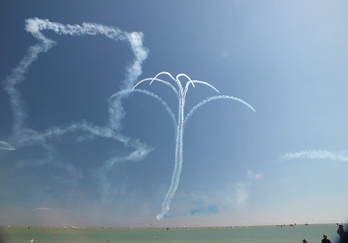
Red Arrows
precision engineering services
Image by afaloon
Airbourne is proud to welcome back the RAF Aerobatic Group, the Red Arrows, a single of the world’s premier aerobatic show teams. 2014 marks a unique year for the team who will be celebrating their 50th show season.

With a trademark combination of close formations and precision flying, the Red Arrows have been displaying considering that 1965 and is made up of a team of 120 men and women including pilots, engineers and support employees. They represent the speed, agility and precision of the Royal Air Force and the public face of the service, assist in recruiting to the Armed Forces and act as ambassadors for the United Kingdom promoting the very best of British.

A lot of of the current pilots were first inspired to pursue a career in the military and join the Royal Air Force following watching the Team in the sky as children.

To apply for selection to the Red Arrows, pilots must:
* Have at least 1,500 quick jet flying hours
* Have completed a frontline tour
* Be assessed as above average in their flying role

The Red Arrows are renowned for the visual impact of their red, white and blue smoke trails. Smoke also plays an critical flight security function also allowing the pilots to judge wind speed and direction – enabling them to locate other aircraft when distinct sections of the Team’s formations are several miles apart.

Aircraft Specifications

Dimensions
Height: 4m
Length: 11.85m
Wingspan: 9.39m

Overall performance
Maximum speed: 622mph

Powerplant
Rolls-Royce Turbomeca Adour Mk 861 turbofan

Lumps of Clay – excerpt thumbnail
precision engineering services
Image by andrewtoskin
a photo comic

words by Andrew Toskin writing as Niccolo Florence

photography by hikaru starr

People have been worrying as well significantly about ebola. How lengthy until you catch children?

Copyright 2014. This function is published beneath a Inventive Commons Attribution-NonCommercial-ShareAlike 4. International License. Which means fundamentally that you’re cost-free to copy and share this operate — provided you credit us as the supply — but not sell it. We are open to the thought of enabling commercial use, even though just ask us 1st. Reposts and remixes of this work should attribute Niccolo Florence and hikaru starr, and hyperlink to curefornightmares.com

Text and images were composited with GIMP. Complete-size JPEGs are here on Flickr.
You’ll also discover the present supply files, plus various exported file formats at
the Net Archive.

Here’s the original comic script:

Panel 1: HIK_4769 edit.JPG — silhouetted loved ones on the
beach, with pier and sunset.

@Title and Byline
&gt Lumps of Clay
words by Niccolo Florence
photography by hikaru starr
curefornightmares.com

caption: I am no one’s father. (However?)

Panel two: IMG_0587.jpg — intense close-up on infant Ema’s face.

caption: But unless or until I succumb, it is my duty
to warn you that *children are harmful.* Stay away
from them anytime feasible.

Panel 3: img_0811.jpg — Ema in a green hoodie in front of
one hundred dangling wooden placards.

caption: If you hear any friends or sexual partners talk about
how their “biological clocks are ticking,” leave the region
and wash your hands. If they *bring* any youngsters with them,
immediately evacuate all childless adults from the vicinity
and notify the nearby authorities.

Panel four: IMG_8976.jpg — Ema peeking around the bole of a
tree, with a creepy statue in the background.

caption: Most individuals are aware of the troubles young children
can trigger, but numerous do not realize the complete extent
of the danger, and so do not take sufficient
precautions. Fortunately, young children do come with a number
of warning indicators to ward off potential adult
caretakers.

Panel five: img_0276 roppongi edit.jpg — Ema’s face covered in red paint(?)

caption: Some of the better known examples consist of the
smells and noise…

Panel 6: HIK_1878.jpg — Ema standing on leading of a statue,
looking down at us.

caption: Less apparent issues: They are also
codependent, irrational, evil creatures, unable to
negotiate or delay gratification. Any individual who shares a
household with a child for extended will slave their days
away to slake ever-altering whims.

Panel 7: IMG_0452.jpg — Ema with a blue onesie more than her
head. Possibly the cutest in the set.

caption: Kids are precision engineered to brainwash
you into loving them.

Panel 8: DSC_4229.jpg — Ema operating to a seesaw in a park.

caption: They will break your things, and break the
bank, and break your dreams, but absolutely nothing is worse than
the techniques they break your heart.

Panel 9: HIK_4865.jpg — Ema seen through a kaleidoscope.

caption: Youngsters are the most insidious of parasites:
The longer they remain with you, the deeper their
tendrils grow into you, cinching your ribs tighter and
tighter around your lungs, slithering into your
nervous technique until you can scarcely believe about
anything else — and then they develop up and leave you.

Panel ten: HIK_0131.jpg — Ema at a shrine, pouring water
over one hand.

caption: And the hole they leave behind just bleeds and
bleeds…

Panel 11: HIK_9941.jpg — Ema wearing an auburn wig.

caption: This is the worst element of all, something that
even most in-individuals who have tested constructive for
children may not recognize for years.

Panel 12: HIK_9841.jpg — black and white Ema holding her
hand up to block the camera.

caption: Since you and your child will drive each
other crazy. *Someone’s* life is receiving ruined, and
you will be terrified that it will not be yours.

caption: You will get in a stupid fight about producing the bed or
some thing and you will both commence screaming and throwing
items, and next thing you know it hits me that I’m
becoming my mother, I’m perpetuating the cycle.

Panel 13: HIK_9310.jpg — Sick Ema in jacket and face mask.

caption: Kids are so fragile, so malleable. Soft
lumps of clay that mold to the contours of your hand
no matter how you try *not* to mold them.

caption: Right after all my blunders, will she be okay? Will
she grow up all proper?

Panel 14: IMG_0567.jpg — singer with guitar and mic.

caption: Could the way she sings in the bathroom be a
sign that she’ll grow up to be a musician?

Panel 15: IMG_8976.JPG — A dancer.

caption: A dancer?

Panel 16: _HIK8727_014-two.jpg — model leaning over glass and handrail.

Panel 17: HIK_5078 raw edit.JPG — kabuki(?) performer on stage.

caption: Some kind of artist, surely.

Panel 18: HIK_1095.jpg — Ema, facing away from the camera.

caption: …Will she be happy?

Panel 19: Huge, complete-page shot. HIK_5285.JPG — Mysterious portrait of Ema
in a hat and daisy dress at night, hunting straight into the camera.

caption: …She isn’t even my daughter. I’ve only met
her once. But I currently enjoy her so much it hurts. I
worry obtaining a youngster of my own would *destroy* me.

End.

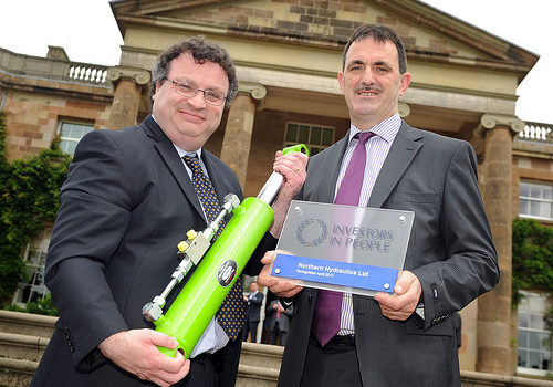
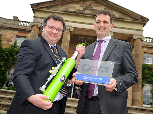
Minister Farry congratulates Seamus Morris of Coalisland’s precision engineering organization Northern Hydraulics on being awarded the prestigious Investors in People (IiP) accreditation

Minister Farry congratulates Seamus Morris of Coalisland’s precision engineering organization Northern Hydraulics on being awarded the prestigious Investors in People (IiP) accreditation

Some cool precision engineering organization photos:

Minister Farry congratulates Seamus Morris of Coalisland’s precision engineering firm Northern Hydraulics on being awarded the prestigious Investors in People (IiP) accreditation
precision engineering company
Image by Northern Ireland Executive
Coalisland precision engineering company Northern Hydraulics is one particular of 37 organisations from across Northern Ireland these days awarded with the prestigious Investors in Folks (IiP) accreditation.

www.northernireland.gov.uk/news-del-250712-northern-hydra…

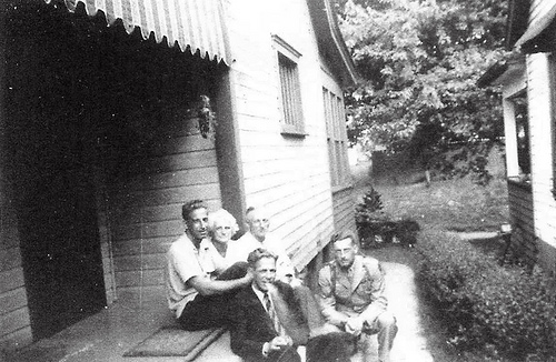
1900s (mid) – Arnold Ray L, Charles L, James R, James Bernard L, Minnie Wilson – 98a8ew8r23
precision engineering company
Image by Rev. Xanatos Satanicos Bombasticos (ClintJCL)
Clint‘s grandad’s family members.

Arnold, Charles, James, Minnie.
sitting, smoking.
military uniform.
black and white.

… Study my weblog at ClintJCL.wordpress.com

Arnold Ray L, my great uncle (dad’s dad’s brother). Born two/18/1906 and died 8/7/1972 in Fairmont, WV.
Son of James and Minnie
Brother of Lena Might, Charles and James Bernard
Occupation: Odd jobs

Charles Edward L, my great uncle (dad’s dad’s brother). Born 9/26/1912 in Fairmont, WV. Died ten/two/1995 in Grand Prarie, TX.
Son of James and Minnie
Husband of Ruth
Father of Susan Miller L, Jayne Albritton L, David, Daniel and Paul
Brother of Arnold Ray, Lena Could and James Bernard
Occupation: Precision Machinist
Charles Edward L served in the Civilian Conservation Corps in the 1930’s where he served as Administrator of a organization sized unit. He served in the WV National Guard from 1930 to 1942. Throughout World War II, he served with his federalized unit in the Territory of Alaska, where he participated in combat against the Japanese.
His principal civilian occupation was Precision Machinist in the aircraft industry. During Planet War II, he worked at his craft on the Manhattan Project (development of the atom bomb) and subsequently worked on a quantity of NASA space rockets. -from ‘Draft Family members History’ as compiled by James Bernard L

James Bernard L, my grandfather (dad’s dad). Born two/18/1922 in Fairmont, WV. Died 12/18/2001 in Arlington, VA.
Son of James and Minnie
Husband of Maria Clara (&quotRonnie&quot)
Father of Victor (dad)
Brother of Arnold Ray, Lena Could and Charles
James Bernard L was a extended-serving member of the 16th Infantry Regiment, 1st Division, and its Association. He joined the National Guard in 1936, then the 16th Infantry in 1940 at Fort Jay, New York. In the Allied landings in Africa in November, 1942, he was the Regimental Sergeant Significant. He fought in Sicily and later, in the Normandy Invasion, as a Warrant Officer beneath General Omar Bradley. He continued with the 16th Infantry through France, the Battle of the Bulge, Germany and Czechoslovakia.
After the war, he served at Fort Knox, Kentucky, the Joint Chiefs of Staff in the Pentagon, Fort Shafter, Hawaii, and the Adjutant GeneralsSchool, Fort Benjamin Harrison, Indiana, exactly where he retired in 1960 as a CWO-four.
James then became one particular of the strongest supporters of the Regimental Association, writing many articles and booklets created by the Association, and was a contributor, editor, and participant in the production of the recent volume of the regiment’s history, &quotBlood and Sacrifice.&quot
James was also an avid flag collector and member of NAVA, and a longtime philatelist.

James Roman L, my excellent-grandfather (dad’s dad’s dad). Born two/13/1884 in Warsaw, Poland. Died 1/28/1965 in Fairmont, WV.
Son of Ignatius and Hegwig?
Husband of Minnie
Father of Arnold Ray, Lena Might, Charles and James Bernard
Brother of Martha and Edward
Occupation: B&ampO Railroad Engineer
James Roman L’s original name was believed to be Julius Roman L. Even though his obituary stated he was born in Warsaw, that is not believed to be the case. He did not know specifically exactly where he was born, but believed it to be &quotsomewhere close to the Russian border.&quot He is buried in the household plot of Jones Cemetery, Fairmont, West Virginia. His name is recorded on the American Immigrant Wall of Honor on Ellis Island, despite the fact that incorrectly listed as James Rome L, from Poland. Our final name implies near the river according to ‘Draft Family members History’ as compiled by James Bernard L.

Minnie Wilson L, my wonderful grandmother (dad’s dad’s mom). Born ten/17/1885 (Mannington, WV). Died 10/1/1971 (Mannington, WV). She had six brothers &amp 3 sisters, 1 husband, 3 sons &amp 1 daughter.
Daughter of Sarepta Alcinda and Nuzum
Wife of James
Mother of Arnold Ray, Lena Could, Charles and James Bernard (Clint‘s grandad)
Sister of Thomas, Martha, Willis, Sanford, Lawrence, Charles, Margaret, Della, Clinton and Naomi
Occupation: Homemaker

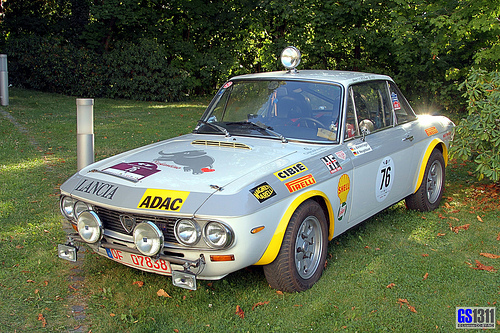
1965 – 1976 Lancia Fulvia Coupé
precision engineering company
Image by Georg Sander
The Lancia Fulvia is an Italian vehicle introduced at the Geneva Motor Show in 1963 by Lancia. It was developed by that firm through 1976. Fulvias are notable for their role in automobile racing history, which includes winning the International Rally Championship in 1972. On testing it in 1967, Road &amp Track summed up the Fulvia as &quota precision motorcar, an engineering tour de force&quot.

(Wikipedia)

– – –

Der Lancia Fulvia ist ein Automobil des italienischen Herstellers Lancia. Es wurde von Herbst 1963 bis Ende 1976 gebaut und gilt als Nachfolgemodell des Lancia Appia.

Wie andere nach dem 1950 vorgestellten Aurelia entwickelten Lancia-Modelle war der Fulvia nach einer klassischen Römerstraße, hier der Through Fulvia, benannt. Im Herbst 1972 wurde dieses Method der Benennung wieder geändert: der unter Fiat-Regie gebaute Nachfolger des Fulvia war der Lancia Beta.

Der Fulvia war als Berlina (Limousine) und als Coupé erhältlich. Außerdem gab es wie bei Lancia üblich ein bei Carrozzeria Zagato entworfenes und in Kleinserie gebautes Fließheckcoupé mit dem traditionellen Namen Sport. Das technische Konzept des Fulvia stammt von Antonio Fessia, die Kind wurde von Pietro Castagnero bei Lancia entworfen.

(Wikipedia)

Good Mechanical Engineering China pictures

Good Mechanical Engineering China pictures

Some cool mechanical engineering china pictures:

Image from web page 182 of “An American engineer in China” (1900)
mechanical engineering china
Image by World wide web Archive Book Images
Identifier: cu31924023226081
Title: An American engineer in China
Year: 1900 (1900s)
Authors: Parsons, William Barclay, 1859-1932
Subjects: Parsons, William Barclay, 1859-1932 Railroads
Publisher: New York, McClure, Phillips &amp co.
Contributing Library: Cornell University Library
Digitizing Sponsor: MSN

View Book Web page: Book Viewer
About This Book: Catalog Entry
View All Pictures: All Images From Book

Click here to view book on the web to see this illustration in context in a browseable on the internet version of this book.

Text Appearing Before Image:
ame on the base, they would beconsidered of Chinese make. They are inex-pensive, of the sort preferred by the Chinaman,although perhaps not for sale in Hamburg orBerlin. On the other hand, the American article,considerably more handsome, from our point of view,but also a lot more high-priced, is of the exact same style as issold on Broadway in New York. There is no want to multiply examples. Thereawaits the American manufacturer an outlet, espe-cially for tools, machinery, and other articles iniron and steel. He will find a demand for thesmaller and lighter machines, rather than for thelarger ones. That is to say, he must appeal firstto the person worker who exists now, ratherthan aim at the needs of a conglomeration in afactory which will come about in the future. The Chapter V: Industrial Relations 177 totals should be basic in character, casil WMirketlami kept in ortler, ami without tlie applicationof fast-return and other mechanical devices s&lttnecessary lor labor-saviiicr with us. Litiht W(jod-

Text Appearing Soon after Image:
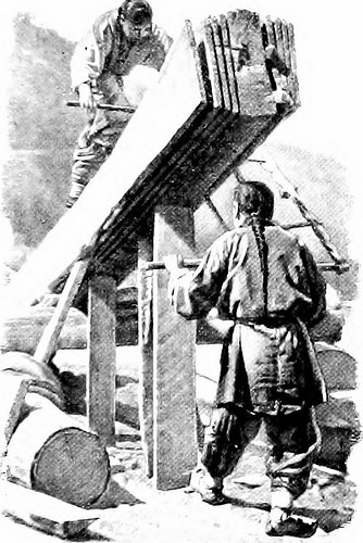
A Chinese Saw-mill The teeth of the saw are arranged to reduce on the up stroke alternatively oton the down, as in other countries operating machiner} can be made to supplant thepresent manual-labnr techniques and a laroe fieldis open for all sorts oi pumps, windmills, piping-,and other articles of Inrlraulic machinerv. Cott(jn g(jods of the finer grades, as properly as the 178 An American Engineer in China coarser which are supplied, household articles ofall kinds, glassware, window-glass, wall-paper,and plumbing fixtures will find a prepared market,as will also farm equipments, such as light-wheeledvehicles and small agricultural implements of allkinds. In these, as in a lot of manufactured arti-cles, American trade has as yet made little or noimpression and yet the American post has anacknowledged superiority over any other for-eign make. It is essential for us also to study the China-man himself. The English and American tradersmake but small try to find out the language, andtherefore frequently f

Note About Pictures
Please note that these images are extracted from scanned web page images that might have been digitally enhanced for readability – coloration and appearance of these illustrations may possibly not perfectly resemble the original function.

Image from web page 124 of “American engineer and railroad journal” (1893)
mechanical engineering china
Image by Internet Archive Book Images
Identifier: americanengineer77newy
Title: American engineer and railroad journal
Year: 1893 (1890s)
Authors:
Subjects: Railroad engineering Engineering Railroads Railroad automobiles
Publisher: New York : M.N. Forney
Contributing Library: Carnegie Library of Pittsburgh
Digitizing Sponsor: Lyrasis Members and Sloan Foundation

View Book Page: Book Viewer
About This Book: Catalog Entry
View All Images: All Photos From Book

Click right here to view book on-line to see this illustration in context in a browseable online version of this book.

Text Appearing Before Image:
co, the firststop to be at Honolulu. From there he goes to Japan, Koreaand Slam, and from China he will travel more than the Trans-Siberian Railroad to Russia. He plans to go to every countryin Europe. Mr. Gross will be absent from this nation abouta year. The goal of his trip is to make a careful investi-gation of the opportunities for American locomotives in theOrient and European nations and to establish systematicbusiness relations. Mr. Gross will be accompanied on his tripby Cliarles M. Muchnic, till recently mechanical engineer ofthe Denver &amp Rio Grande, who will act as Mr. Gross secretary. Mr. Max Toltz has resigned as mechanical engineer of theGreat Northern Railway. He is engaged in superintendingthe application of his system of acetylene car lighting to alarge quantity of vehicles on the Canadian Pacific, and has beenretained by that road in a consulting engineering capacity inconnection with the new shops at Montreal. March, 1903. AMERICAN ENGINEER AND RAILROAD JOURNAL. Ill

Text Appearing After Image:
nniDD DD

Note About Pictures
Please note that these images are extracted from scanned page images that may have been digitally enhanced for readability – coloration and look of these illustrations could not completely resemble the original operate.

110824-N-XR557-038
mechanical engineering china
Image by Cooperation Afloat Readiness and Coaching (CARAT)
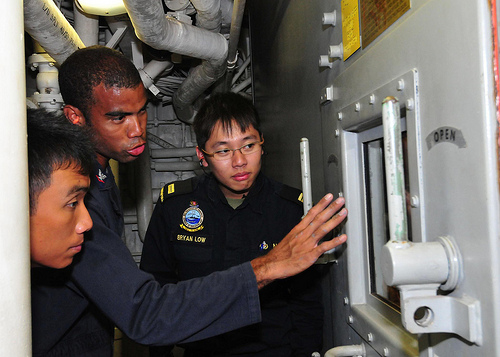
110824-N-XR557-038 SOUTH CHINA SEA (Aug. 24, 2011) Gas Turbine Systems Technician (Mechanical) 3rd Class Earl Bellamy, center, of the guided missile destroyer USS Chung-Hoon (DDG 93) shows Republic of Singapore Navy officers 2nd Lt. Dominic Lew, left, and Lt. Bryan Low, right, the propulsion gas turbine module during a tour of the engineering spaces whilst underway for Cooperation Afloat Readiness and Training (CARAT) Singapore 2011. CARAT 2011 is a series of bilateral workout routines held annually in Southeast Asia to strengthen relationships and boost force readiness. (U.S. Navy photo by Mass Communication Specialist 2nd Class Katerine Noll/Released)

Cool Higher Precision Engineering images

Cool Higher Precision Engineering images

Check out these high precision engineering pictures:

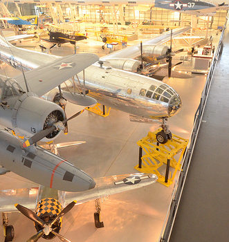
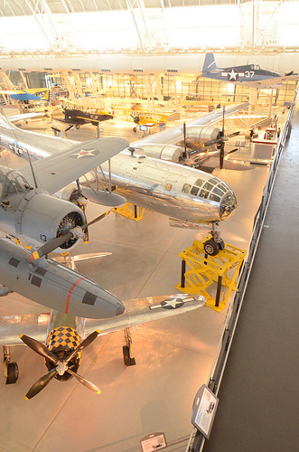
Steven F. Udvar-Hazy Center: South hangar panorama, such as Vought OS2U-three Kingfisher seaplane, B-29 Enola Gay
high precision engineering
Image by Chris Devers
Quoting Smithsonian National Air and Space Museum | Vought OS2U-3 Kingfisher:

The Kingfisher was the U.S. Navy’s primary ship-based, scout and observation aircraft throughout Globe War II. Revolutionary spot welding strategies gave it a smooth, non-buckling fuselage structure. Deflector plate flaps that hung from the wing’s trailing edge and spoiler-augmented ailerons functioned like further flaps to allow slower landing speeds. Most OS2Us operated in the Pacific, exactly where they rescued numerous downed airmen, including World War I ace Eddie Rickenbacker and the crew of his B-17 Flying Fortress.

In March 1942, this airplane was assigned to the battleship USS Indiana. It later underwent a six-month overhaul in California, returned to Pearl Harbor, and rejoined the Indiana in March 1944. Lt. j.g. Rollin M. Batten Jr. was awarded the Navy Cross for generating a daring rescue in this airplane beneath heavy enemy fire on July four, 1944.

Transferred from the United States Navy.

Manufacturer:
Vought-Sikorsky Aircraft Division

Date:
1937

Nation of Origin:
United States of America

Dimensions:
Overall: 15ft 1 1/8in. x 33ft 9 1/2in., 4122.6lb., 36ft 1 1/16in. (460 x 1030cm, 1870kg, 1100cm)

Supplies:
Wings covered with fabric aft of the major spar

Physical Description:
Two-seat monoplane, deflector plate flaps hung from the trailing edge of the wing, ailerons drooped at low airspeeds to function like further flaps, spoilers.

• • • • •

Quoting Smithsonian National Air and Space Museum | Boeing B-29 Superfortress &quotEnola Gay&quot:

Boeing’s B-29 Superfortress was the most sophisticated propeller-driven bomber of Globe War II and the very first bomber to house its crew in pressurized compartments. Although created to fight in the European theater, the B-29 located its niche on the other side of the globe. In the Pacific, B-29s delivered a assortment of aerial weapons: conventional bombs, incendiary bombs, mines, and two nuclear weapons.

On August 6, 1945, this Martin-constructed B-29-45-MO dropped the first atomic weapon utilised in combat on Hiroshima, Japan. Three days later, Bockscar (on display at the U.S. Air Force Museum close to Dayton, Ohio) dropped a second atomic bomb on Nagasaki, Japan. Enola Gay flew as the advance climate reconnaissance aircraft that day. A third B-29, The Fantastic Artiste, flew as an observation aircraft on each missions.

Transferred from the United States Air Force.

Manufacturer:
Boeing Aircraft Co.
Martin Co., Omaha, Nebr.

Date:
1945

Nation of Origin:
United States of America

Dimensions:
All round: 900 x 3020cm, 32580kg, 4300cm (29ft six five/16in. x 99ft 1in., 71825.9lb., 141ft 15/16in.)

Supplies:
Polished overall aluminum finish

Physical Description:
Four-engine heavy bomber with semi-monoqoque fuselage and higher-aspect ratio wings. Polished aluminum finish all round, normal late-World War II Army Air Forces insignia on wings and aft fuselage and serial quantity on vertical fin 509th Composite Group markings painted in black &quotEnola Gay&quot in black, block letters on reduced left nose.

Nice Cnc Engineering Solutions pictures

Nice Cnc Engineering Solutions pictures

A handful of nice cnc engineering services images I discovered:

Blackened steel stair with stainless treads
cnc engineering services
Image by Caliper Studio
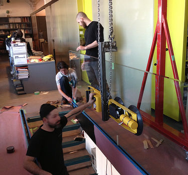
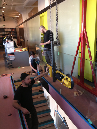
Center stringer comfort stair connects two office floors in Starret Lehigh constructing. Stringer and slab edge assemblies are blackened. Twenty 4 stainless steel treads are welded to the stringer kind a continuous ribbon. 1 1/four&quot diameter handrail posts are continuous bent &quotC&quot shapes that wrap about treds and are welded to stringer. Stair will be delivered to website in one particular piece [24′ extended 3′ wide 3′ tall @ 2000lbs].

Style by Diller Scofidio + Renfro

Detailing, Fabrication and Installation by Caliper Studio. Caliper Studio engaged Eckersley O’Callaghan &amp partners for engineering services.

Cool Machining Engineering pictures

Cool Machining Engineering pictures

A few good machining engineering images I discovered:

Image from page 340 of “Engineering and Contracting” (1909)
machining engineering
Image by Net Archive Book Pictures
Identifier: engineeringcontr33chicuoft
Title: Engineering and Contracting
Year: 1909 (1900s)
Authors:
Subjects:
Publisher: Chicago
Contributing Library: Gerstein – University of Toronto
Digitizing Sponsor: MSN

View Book Page: Book Viewer
About This Book: Catalog Entry
View All Pictures: All Images From Book

Click here to view book on the internet to see this illustration in context in a browseable on-line version of this book.

Text Appearing Just before Image:
er, Wyo. T. E. Calvert,Chicago, 111., is chief engineer. 200 ENGINEERING-CONTRACTING Vol. XXXIII. No. q. A New Jaw Crusher Made Particu-larly for Contractors Use. .A. crusher for contractors use has to ful-fill distinct specifications than are intendedfor general quarry use. A contractorscrusher should be of large output, remarkablylight in weight, convenient to deal with and aboveall really durable. Certain focus hasbeen paid to these qualities in designing thecrusher illustrated in the accompanying cut.A notable function of this machine is its prac- Approach of Generating a Steam Shovel Cutof Two Lifts in 1 Lift. BY H. MORTON STEPHENS.* During September, 1909. the E. Purcell Con-struction Co., secured from the Winston-Salem South Bound Ry. Co., a contract forthe building of part of tJie above railroad,embracing sections 22 to 30 inclusive. Section22 is positioned in the town of Lexington, N. C,on the Southern Ry. The balance of the workruns south by way of a rolling country, and with

Text Appearing Soon after Image:
A New Jaw Crusher for Contractors. tically all-steel construction. The major frameor side plates are of rolled steel plates. Thelarge casting that forms the front of themachine, which part is termed the stationaryjaw, is of grey iron. The moving or swingingjaw is a steel casting. The tumbler or largelever casting is also of steel. The fly wheelsand pedestals are of grey iron. The maincam shaft and the anti-friction roller are steelforgings. The anti-friction roller revolvesin boxes produced of unique bronze material. Allshafts from which castings are suspended areof steel. The cheek plates are of unique har-dened steel, although the toggle seats are alsomade of unique steel. This steel construction makes the machineof tremendous strength in comparison withits size. The feeding mouth is reduce, in fact,than in other crushers of equal size. Thismeans that a huge saving is effected in deliv-ering stone into the crusher. The crusherwill turn out from 150 to 200 tons of crushedmaterial per day

Note About Photos
Please note that these photos are extracted from scanned page images that may have been digitally enhanced for readability – coloration and appearance of these illustrations may possibly not completely resemble the original work.

Image from web page 490 of “Railway and locomotive engineering : a sensible journal of railway motive power and rolling stock” (1901)
machining engineering
Image by World wide web Archive Book Images
Identifier: railwaylocomotiv19newy
Title: Railway and locomotive engineering : a practical journal of railway motive energy and rolling stock
Year: 1901 (1900s)
Authors:
Subjects: Railroads Locomotives
Publisher: New York : A. Sinclair Co
Contributing Library: Carnegie Library of Pittsburgh
Digitizing Sponsor: Lyrasis Members and Sloan Foundation

View Book Web page: Book Viewer
About This Book: Catalog Entry
View All Pictures: All Photos From Book

Click here to view book on-line to see this illustration in context in a browseable on the internet version of this book.

Text Appearing Ahead of Image:
ops, as a result loses a gooddeal of its mobility. The two motortrucks o.f our locomotive are truebogies, totally free to assume all|)ositions on the track. Its boiler rests1111 a frame produced of a beamiif which tlie ends are enlarged Exhibits, Traveling EngineersConvention. American Locomotive Equipment Co.,Chicago, showed a chart of test of thehollow arch compared with the solidarch and no arch. S. F. Bowser &amp Co., Inc., Fort Wayne,Ind., distributed circulars showingBowser oil storage method as utilised at lo-comotive stations. Century Preserver Co. distributed,by way of their sales agent, W. A. Ahrens,Chicago, some literature concerningtheir black metal preserver for coveringIhe exposed surfaces of metal. The Chicago Pneumatic Tool Com-pany have just issued their new Com-pressor catalogue consisting of 118p?ges, printed in two colors. Severalnew sorts and sizes of Compressors areshown in this catalogue including theirItw Hamilton Corliss Machines. Thoseinterested will obtain copy upon re-

Text Appearing Soon after Image:
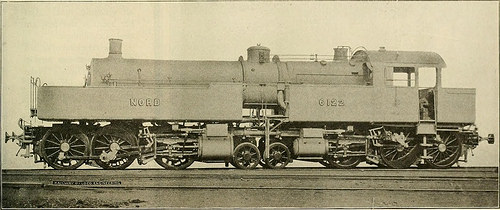
TANK ENGINE FOR THE CHEMIN DE FER DU NORD, FRANCE. ins. The diameter of the boiler is 51ins. There are 130 tubes every about 15ft. 7 ins. long and there is a total heat-ing surface of tubes and fire box of2,361 sq. ft. The pressure carried is228 lbs. to the square inch. Steam fromthe boiler goes to the cylinders andthrough them to the smoke box throughthe steam pipe which runs from thedome down to a swivel joint placed overthe kingpin of the truck with its axisin line with the kingpin. From the highpressure cylinders it goes to the lowpressure cylinders via a length offlexible pipe. The exhaust is led to thesmoke box by way of one more swivel jointin the center of the truck carrying thelow pressure cylinder. An arrangementis created whereby both the high and thelow stress cylinders may be suppliedwith high pressure steam when neces-sary, in starting or on grades. In thiscase the engine operates as a basic and offered with signifies for at-taching the elastic springs. Thisarrangement, com

Note About Pictures
Please note that these photos are extracted from scanned web page images that may have been digitally enhanced for readability – coloration and appearance of these illustrations may not perfectly resemble the original operate.

Royal Engineers total construction of Afghan Nearby Police station in Helmand capital
machining engineering
Image by DVIDSHUB
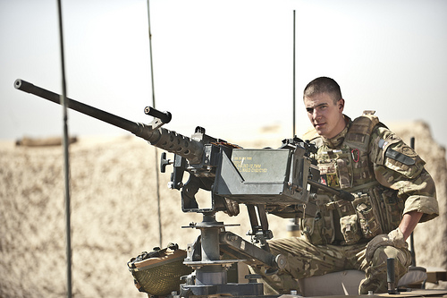
Highlander Mark Mackenzie, 4th Battalion, The Highlanders, Royal Regiment of Scotland, and a native of Stoneaway, Scotland, completes a final check of a .50-caliber mounted machine gun ahead of delivering security for 59 Commando Squadron, Royal Engineers, as they travel to construct an Afghan Neighborhood Police station in Lashkar Gah District, Helmand province, July 24. The Engineers constructed the station for the Afghan Nearby Police, a local safety force produced up of hand-picked people from the neighborhood.
Regional Command Southwest
Photo by Petty Officer 2nd Class Jonathan Chandler
Date Taken:07.24.2011
Place:HELMAND PROVINCE, AF
Connected Pictures: dvidshub.net/r/khgcep

Nice Prototype Engineering images

Nice Prototype Engineering images

A couple of nice prototype engineering pictures I discovered:

Japanese Tank Sort 95 Ha-Gō (九五式軽戦車 ハ号 Kyugoshiki keisensha Ha-Gō). 1935. Японский танк Тип 95 “Ха-Го”.
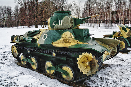
prototype engineering
Image by Peer.Gynt
Poklonnaya Gora WWII Museum. Moscow.
Поклонная гора. Москва.

Specifications
Weight – 7,400 kilograms
Length – four.38 m
Width – 2.06 meters
Height- two.18 meters
Crew – 3

Main armament Type 94 37 mm gun
Secondary armament Type 91 six.5 mm machine gun or 2 x Type 97 7.7 mm machine gun
Engine Mitsubishi NVD 6120 air-cooled diesel 120 hp (89 kW)
Suspension Bell crank
Operational range250 kilometers
Speed 45 km/h (road)

The Kind 95 Ha-Gō (九五式軽戦車 ハ号 Kyugoshiki keisensha Ha-Gō?) (also recognized as the Type 97 Ke-Go) was a light tank employed by the Imperial Japanese Army in combat operations of the Second Sino-Japanese War and the Second Globe War. Despite the fact that it was quite slow for a light tank, it proved sufficient against opposing infantry in campaigns in Manchuria and China, as the Chinese National Revolutionary Army had very handful of tanks or anti-tank weapons to oppose them. However, the Kind 95 lacked the armor or armament of contemporary Allied tanks, and was regarded as obsolete by the begin of World War II. Much more than 2,000 units were produced. It was also employed by Imperial Japanese Navy SNLF detachments in Pacific locations during conflict.
History and improvement

From early 1930s, the Japanese army began experimenting on a mechanized warfare unit combining infantry with tanks. Nevertheless, the Variety 89 Medium tank could not maintain pace with the motorized infantry, which could move at 40 km/h by truck. To resolve this issue, the Army Technical Bureau proposed a new light tank at 40 km/h speed and began development in 1933. The prototype of the new tank was completed in 1934 at the Army’s Sagami Arsenal. It was a higher-speed and lightly-armored tank comparable to the British cruiser tank or Soviet BT tank. Its code name was &quotHa-Gō&quot (ハ号) designated that it was the &quotthird variety&quot of tank developed.[three]

In 1935, a meeting was held at the Army Technical Bureau, at which time, the Sort 95 was presented as a potential principal battle tank for mechanized infantry units. The infantry had issues that the armor was not thick sufficient for sufficient infantry support nonetheless, the cavalry indicated that the improved speed and armaments compensated for this thin armor. In the end, the infantry agreed, as the Kind 95 was nevertheless superior to the only offered option, which was the armored car.

Production was started in 1935 by Mitsubishi Heavy Industries. By 1939, 100 units had been constructed. Mitsubishi would go on to create a total of 853 in their personal factories, with yet another 1250 units constructed by the Sagami Arsenal, Hitachi Industries, Niigata Tekkoshō, Kobe Seikoshō, and Kokura Arsenal.[two]

Type 95 Ha-Go tanks in New Britain following the Japanese surrender

Variety 95 on show at the United States Army Ordnance Museum, front view

Correct side view.

Type 95 at Tarawa

The Type 95 was a major improvement more than the Japanese Army’s prior light tanks and tankettes, but was soon involved in an intensive plan to make enhanced variants such as the Manshū model (Type M), the Ha-Gō’s direct descendant. Sort M was technically identical but created for use in the Kwantung Army’s tank schools in Manchukuo and it was planned to be provided in far far more numbers to future Manchukuo Imperial Army armored units and was projected to be manufactured in that country.

One more improvement was the Kind 98 Ke-Ni light tank that entered production in 1942 of which 200 autos had been constructed. This derivitative was better armored and carried an armament comprising one particular Variety 100 37 mm gun and two 7.7 mm machine guns.

The Kind 95 also served as the basis of the Type 2 Ka-Mi amphibious tank which gave good service in Japan’s early campaigns of Globe War II.

[edit]
Design and style

The Type 95 was a 7.4-ton vehicle with a complement of 3 crewmen (normally a commander/gunner/loader, mechanic/bow machine gunner, and a driver).

The main armament was one particular Sort 94 37 mm Tank Gun with 37 mm caliber, barrel length of 1.3585 meters (L36.7) (early model), 1.358 meters (L36.7) (late model), el angle of fire -15 to +20 degrees (early model), -15 to +20 degrees (late model), AZ angle of fire of 20 degrees (early model) 20 degrees (late model), muzzle velocity: 600 m/s (early model), 700 m/s (late model), penetration: 45 mm/300 m (early model) 25 mm/500 m (late model) utilized by the Kind 95 Light Tank. The commander was accountable for loading, aiming, and firing the primary gun, The Kind 95 tank carried two sorts of ammunition, Kind 94 high-explosive and Type 94 armor-piercing.

Secondary armament consisted as two Type 91 six.5mm machine guns, 1 mounted in the hull and the other in the turret facing to the rear. Trial use in Manchukuo and China confirmed that much better armament was desirable and the 6.5mm machine guns had been exchanged for more powerful 7.7mm Sort 97 light machine guns on the appropriate hand side, for use by the currently overworked commander/gunner in 1941. The original Type 94 major gun was also replaced with a Kind 98 weapon of the identical caliber but with a larger muzzle velocity.

The hand-operated turret was little and very cramped for even the one particular crewman normally located there (the commander), and was only becoming able to rotate in a 45 degree forward arc, leaving the back to be covered by the rear-facing machine gun which failed to compensate for this significant disadvantage.

The most characteristic feature of the Kind 95 tank was its simple suspension system. The tracks had been driven through the front sprocket. Two bogie wheels have been suspended on a single bell crank with two bell cranks per side. There had been two return wheels. The suspension had troubles early on with a tendency to pitch so badly on rough ground that the crew at times located it impossible to drive at any speed, and so it was modified with a brace to connect the pairs of bogies. Despite this, the tank continued to give its users a rough ride across any uneven ground, and was provided with an interior layer of asbestos, valuable in reducing interior heat and defending the crew from injury when the tank moved at high speed across rough terrain.[3]

This initial production models employed one particular 110 hp (82 kW) Mitsubishi air cooled diesel engine with a leading speed of 25 mph (40 km/h). This was the exact same engine that equipped the Kind 89 I-Go medium tank. Later the much more potent engine Mitsubishi NVD 6120 with 120 hp (89.five kW) was installed.[3] Some Variety 95 had been fitted with two reflectors in the front of the automobile for night operations.

[edit]
Variants

Type 95 tank in Bovington tank museum, Dorset

Type 95 on show at the Battery Randolf US Army Museum, Honolulu, top rear view

Kind 95 Ha-Go tanks destroyed by an Australian two pounder gun in the Battle of Muar

A single of six Ha-Go tanks destroyed by an Australian 2 pounder gun in the Battle of Muar. The escaping crew had been killed by allied infantry covering the artillery
Kind three Ke-Ri
This was a proposed model with a Type 97 57 mm gun as the principal armament. This design in no way got previous testing in 1943.
Variety 4 Ke-Nu
The Variety 4 Ke-Nu was intended to address one of the most widespread complaints about the Kind 95 from its customers – the cramped turret. The current Sort 95 turret was replaced by the turret of a Kind 97 Medium tank for more space. About 100 units had been made.
Sort 95 Manshū
The Kind 95 Manshū was an operational and training tank derived from and really comparable to the Kind 95 Ha-Gō. These tanks were detached to Manchukuo and belonged to the instruction unit of the Kwantung Army tank college.
Variety 95 &quotTa-Se&quot Anti-Aircraft Tank
An experimental car known as &quotTa-Se&quot was built in November 1941, utilizing the chassis of Sort 95 Ha-Gō with a 20 mm anti-aircraft gun taken from the Type 98 20 mm anti-aircraft gun. Another version utilised a Type two 20 mm anti-aircraft gun. Neither model went into production.
Sort 2 Ka-Mi Amphibious Tank
This was the 1st amphibious tank created in Japan, and was intended for use by the Navy’s SNLF. The pontoons could be detached after landing by a fourth crewman from inside the tank. The chassis was primarily based on the Variety 95 Light Tank. The Type 2 Ka-Mi was encountered by the United States Marine Corps in the Marshall Islands and Mariana Islands, especially on Guam, exactly where it was utilized in static defense positions.
Variety 95 &quotRi-Ki&quot Crane Car
The Sort 95 Ri-Ki was an engineering car for field functions. It had a 3-ton 4.five meter boomed crane.
120 mm self-propelled gun &quotHo-To&quot
The Kind 95 Ho-To was a Sort 38 120 mm howitzer mounted on the Sort 95 Ha-Go chassis. The gun was low-velocity but the HEAT shell enabled it to destroy the American M4 Sherman tank. This self-propelled gun was developed along with the Ho-Ru self-propelled gun.
Sort five Ho-Ru 47 mm self-propelled gun
The Ho-Ru was a light tank destroyer equivalent to the German Hetzer. The improvement of the Sort five Ho-Ru started in February 1945. The Variety five Ho-Ru utilized the chassis of the Variety 95 Light Tank, but its suspension was enlarged to 350 mm track hyperlink width. The wheel guide pins had been set in two rows to hold a road wheel among them. The sprocket of the driving wheel was the grating variety to gear with the wheel guide pins like on the Soviet T-34. It was armed with one particular 47 mm primary gun.
Variety 98 Ke-Ni light tank
This final modification was somewhat lighter than the original Variety 95, even with its heavier (.62 inch) armor. It entered production in 1942, but only about 200 were manufactured.

[edit]
Combat history

When the Kind 95 entered service in 1935 it was a capable machine and comparable to any contemporary light tank in the globe. It was the very best car of its category offered to the Japanese forces in any numbers from the 1930s to World War II, and was utilised mostly to assistance infantry or as cavalry reconnaissance and, to a lesser extent, as raiding cars. It could compete with the American M3 light tanks on the Philippines, while the British had really couple of tanks of any kind in Malaya or Burma in December 1941. [4]

The Variety 95 Ha-Gō proved moderately successful for the duration of the early campaigns of late 1941 and early 1942, when Japanese forces overran British Malaya and seized the fortress city of Singapore. A single important to the Japanese good results in Malaya was the unexpected presence of their tanks in places exactly where the British did not believe tanks could be employed. The wet jungle terrain did not turn out to be an obstacle twelve Kind 95s took part in the attack which broke the Jitra line on 11 December 1941.

The very first tank-vs-tank battles of the war was on 22 December 1941 for the duration of the Japanese invasion of the Philippines. Variety 95s of the 4th Tank Regiment clashed with M3s of the American 192nd Tank Battalion. Both tanks had been armed with a 37 mm gun, and the M3 was better armored nevertheless, the inexperienced American commanders failed to make good use of their tanks.

Two Variety 95 tanks were deployed to assistance the Japanese landing at Milne Bay, late August 1942. Initially, the tanks proved successful against the lightly armed Australian infantry, whose ‘sticky bombs’ failed to stick due to the humidity. Even though the tanks had proved trustworthy in the tropical circumstances of Malaya, they could not deal with the volume of mud brought on by intense, virtually everyday rainfall at Milne Bay. Each tanks had been bogged down and abandoned a handful of days right after the landing.

The Sort 95 very first began to show its vulnerability in the course of later battles against British/Commonwealth forces, where the tank’s 37mm gun could not penetrate the armor of the British Matilda tanks which have been deployed against them. The thin armor of the Variety 95 made it increasingly vulnerable as Allied forces realized that common infantry weapons have been capable of penetrating the minimal armor about the engine block, and even its thickest armor could not withstand anything above rifle caliber. Its firepower was insufficient to take on other tanks such as the medium M4 Sherman or the M3 Stuart light tanks. [4]

As the tide of the war turned against Japan, the Sort 95s had been escalating expended in banzai charges or were dug-in as pillboxes in static defense positions in the Japanese-occupied islands. During the Battle of Tarawa, seven entrenched Type 95th opposed American landings. More have been destroyed on Parry Island and on Eniwetok. On Saipan, Sort 95s attacked the American Marine beachhead on 16 June 1944 and much more were utilized in the largest tank battle in the Pacific the following day.

In the Battle of Guam on 21 July, ten Kind 95 had been lost to bazooka fire or M4 tanks. Seven a lot more had been destroyed on Tinian on 24 July, and 15 much more on Battle of Peleliu on 15 September. Likewise, in the Philippines, at least ten Variety 95s have been destroyed in various engagements on Leyte, and yet another 19 on Luzon. At the Battle of Okinawa, 13 Type 95s and 14 Type 97 Shihoto medium tanks of the 27th Tank Regiment faced 800 American tanks.

When the war ended hundreds of Type 95s have been left in China. They had been used for the duration of the Chinese Civil War and by the People’s Liberation Army of the People’s Republic of China throughout the Korean War.

Soviet Higher-Speed Tank BT-two. Советский быстроходный танк БТ-two.
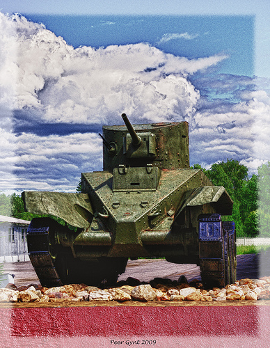
prototype engineering
Image by Peer.Gynt
The BT tanks (Russian: Быстроходный танк (БТ), Bystrokhodny tank, lit. &quotfast tank&quot or &quothigh-speed tank&quot) were a series of Soviet cavalry tanks produced in big numbers in between 1932 and 1941. They have been lightly armoured, but reasonably nicely-armed for their time, and had the best mobility of all modern tanks of the planet. The BT tanks have been known by the nickname Betka from the acronym, or its diminutive Betushka.

The direct successor of the BT tanks would be the well-known T-34 medium tank, introduced in 1940, which would replace all of the Soviet quick tanks, infantry tanks, and medium tanks in service.
Design and style

The BT tanks had been &quotconvertible tanks&quot. This was a function made by J. Walter Christie to decrease put on of the unreliable tank tracks of the 1930s. In about thirty minutes the crew could get rid of the tracks and engage a chain drive to the rearmost road wheel on each side, enabling the tank to travel at very higher speeds on roads. In wheeled mode the tank was steered by pivoting the front road wheels. Even so, Soviet tank forces soon discovered the convertible selection of little practical use in a country with handful of paved roads, and it consumed space and added needless complexity and weight. The feature was dropped from later Soviet styles.

Christie, a race vehicle mechanic[citation needed] from New Jersey, had tried unsuccessfully to convince the U.S. Army Ordnance Bureau to adopt his Christie tank style. In 1930, Soviet agents at Amtorg, ostensibly a Soviet trade organization, utilized their New York political contacts to persuade U.S. military and civilian officials to give plans and specifications of the Christie tank to the Soviet Union. At least two of Christie’s M1931 tanks (without having turrets) had been later bought in the United States and sent to the Soviet Union below false documentation in which they have been described as &quotagricultural tractors.&quot[citation necessary] Both tanks were effectively delivered to the Kharkov Komintern Locomotive Plant (KhPZ). The original Christie tanks have been designated quick tanks by the Soviets, abbreviated BT (later referred to as BT-1). Based both on them and on previously obtained plans, three unarmed BT-two prototypes have been completed in October 1931 and mass production started in 1932. Most BT-2s have been equipped with a 37 mm gun and a machine gun, but shortages of 37 mm guns led to some early examples getting fitted with three machine guns.

The sloping front hull (glacis plate) armor design and style of the Christie M1931 prototype was retained in later Soviet tank hull styles, later adopted for side armor as properly.

The BT-five and later models were equipped with a 45 mm gun.

BT-1: Christie prototype with no turret.
BT-two Model 1932: M-five-400 engine (copy of U.S. Liberty engine), 3 modifications of turret produced: with single 37 mm gun 37 mm gun and 1 DT machine gun twin DP machine guns mount and a single machine gun. In late 1932 modified to BT-three but created beneath identical designation.
BT-3: exact same as BT-2, developed according to metric program (rather of Imperial system as employed for BT-two). In official documentation referred to as BT-2.
BT-four: was a design and style with welded hull and minor modifications in the suspension. 3 prototypes made (with partially riveted hull)
BT-five: bigger cylindrical turret, 45 mm gun, coaxial DT machine gun. BT-five Model 1933: new turret with twin hatches and larger bustle.
BT-5PKh: snorkelling variant (prototypes only).
BT-5A: artillery assistance version with 76.two mm howitzer (few made).
BT-five flamethrower tank: (prototypes only).
PT-1A: amphibious variant with new hull (couple of made).

BT-7 Model 1935: welded hull, redesigned hull front, new Mikulin M-17T engine (licensed copy of a BMW engine), enclosed muffler. BT-7 Model 1937: new turret with sloping armour.
BT-7TU: command version, with whip antenna rather of earlier frame antenna.
BT-7A: artillery assistance version with 76.2 mm howitzer.
OP-7: flame-thrower version with external fuel panniers (prototype only).

BT-7M[3] (1938, prototypes designated A-eight sometimes referred to as BT-8): new V-two diesel engine replacing earlier gasoline engines, 3 DT machine guns: coaxial, in P-40 AA mount on roof and in a ball-mount on turret rear.
BT-42: Finnish assault gun captured BT-7s had been equipped with British 114 mm howitzers.
BT-43: Finnish armoured personnel carrier captured BT-7s equipped with troop accommodation.
BT-IS: Prototype/proof-of-idea platform with heavily sloped armor forerunner of the armor style on the T-34.
BT-SW-2 Cherepakha (&quotturtle&quot): Yet another prototype, which took the armour sloping to an intense.
A-20: Prototype for a new BT tank, with 20 mm armour, 45mm gun, model V-2 diesel engine, and 8×6-wheel convertible drive. Lost out in trials to the A-32, which was further enhanced and produced as the T-34 medium tank.
TTBT-five, TTBT-7: teletanks, remote-controlled tanks.

Combat history

BT tanks saw service in the Spanish Civil War, Battle of Khalkhin Gol (Nomonhan), the Winter War in Finland, the Polish campaign, and in the whole Globe War II.
They first saw action in the Spanish Civil War. A battalion of BT-5s fought on the Republican side, and their 45 mm guns could easily knock out the opposing German and Italian light tanks
Battle of Khalkhin Gol (Nomonhan)
See also: Soviet–Japanese Border Wars
For the duration of the Battles of Khalkhin Gol (also identified as the Nomonhan Incident), which lasted from May possibly to September in 1939, BT tanks have been simply attacked by Japanese &quotclose quarter&quot teams (tank killer squads) which had been armed with petrol bottles (later named &quotMolotov Cocktails&quot). The Soviet BT-five and BT-7 light tanks, which had been operating in temperatures higher than 100F on the Mongolian plains, effortlessly caught fire when a molotov cocktail ignited their gasoline engines.Basic Georgy Zhukov produced it a single of his &quotpoints&quot when briefing Joseph Stalin, that his &quot…BT tanks were a bit fireprone….&quot Conversely, numerous Japanese tankers held the Soviet 45mm anti-tank/tank guns in high esteem, noting, &quot…no sooner did they see the flash from a Russian gun, than they’d notice a hole in their tank, adding that the Soviet gunners were accurate as well!&quot
Right after the Khalkhin Gol War in 1939, the Soviet military had broken into two camps one particular side was represented by Spanish Civil War veterans Common P. V. Rychagov of the Soviet Air Force, Soviet armour expert Common Dimitry Pavlov, and Stalin’s favourite, Marshal Grigory Kulik, Chief of Artillery Administration.[16] The other side consisted of the Khalkhin Gol veterans led by Generals Zhukov and G.P. Kravchenko of the Soviet Air Force.[17] Beneath this cloud of division, the lessons of Russia’s &quotfirst real war on a huge scale using tanks, artillery, and airplanes&quot at Nomonhan (Khalkhin Gol) went unheeded. Consequently, for the duration of the Finland War (Winter War) the BT-two and BT-5 tanks were less profitable, and it took the Soviet Union 3 and a half months, and more than a million males to do what Zhukov did in just ten days at Nomonhan.
Following the German war broke out, the Spanish Civil War faction fell in disfavor, with Marshal Kulik in specific getting court-martialed and demoted. Gen. Zhukov and the majority of his surviving Nomonhan veterans were appointed to commands throughout European Russia, in time to engage the German armies.
Globe War II
Throughout the Second World War, BT-5 and BT-7 tanks have been utilized in the 1939 Soviet invasion of Poland, and in large numbers in the battles of 1941 – in the course of which thousands had been abandoned or destroyed. A handful of remained in use in 1942, but were uncommon following that time. The Red Army planned to replace the BT tank series with the T-34, and had just begun doing so when the German invasion (Operation Barbarossa) took location.
In the course of the final weeks of World War II, a significant quantity of BT-7 tanks took element in the invasion of Japanese-occupied Manchuria, in August 1945. This was the last combat action of BT tanks.
Technical legacy

The BT tank series was several, forming the cavalry tank arm of the Red Army in the 1930s, and had significantly better mobility than other contemporary tank designs. For these reasons, there had been several experiments and derivatives of the design and style, largely carried out at the KhPZ factory in Kharkov.
The most important legacy of the BT tank was the T-34 medium tank, arguably the most essential tank of the entire World War II. In 1937, a new design and style team was formed at the KhPZ to create the subsequent generation of BT tanks. Initially, the chief designer was Mikhail Koshkin and, following his death, Morozov. The group constructed two prototypes. The light one particular was called the A-20. The much more heavily armed and armoured BT derivative, the A-32, was a &quotuniversal tank&quot to replace all the T-26 infantry tank, BT cavalry tanks, and the T-28 medium tanks. Such plan was controversial, but issues about tank overall performance beneath the threat of German blitzkrieg led to the approval for production of a nevertheless more heavily-armoured version, the T-34 medium tank.
Along the way, an essential technical development was the BT-IS and BT-SW-2 testbed automobiles, concentrating on sloped armour. This proof-of-concept led straight to the armour layout of the T-34.
BT tank chassis have been also used as the basis for engineering assistance autos and mobility testbeds. A bridgelayer variant had a T-38 turret and launched a bridge across modest gaps. Normal tanks have been fitted as fascine carriers. The RBT-5 hosted a pair of large artillery rocket launchers, a single on every single side of the turret. Many designs for incredibly wide tracks, like, oddly, wooden ‘snowshoes’ had been attempted on BT tanks.
The KBT-7 was a completely modern day armoured command automobile that was in the prototype stage when Planet War II broke out. The design and style was not pursued for the duration of the war.
In the Kiev maneuvers of 1936, foreign military observers have been shown hundreds of BT tanks roll by a reviewing stand. In the audience had been British Army representatives, who returned residence to advocate for use of Christie suspension on British cruiser tanks which they incorporated from the Cruiser Mk III onwards. Interestingly, the pointed shape of the hull front armor on the BT tank also influenced the design of the British Matilda tank.
Copycad In Reverse Engineering

Copycad In Reverse Engineering

As a implies of sophisticated solution style, reverse engineering in China are now far more and much more significance in enterprises, reverse technologies, consideration of a lot more and much more broadly. Reverse Engineering (Reverse Engineering) project idea: By way of the existing solution model three-dimensional digital scanning, to obtain the solution model of the surface contour of the point cloud data, the point cloud data processed by specialized software program and ultimately the formation of three-dimensional mathematical model for item re-design and CNC machining and structural analysis. It is diverse from our usual two-dimensional sketches by the 3-dimensional model of design to design and then to processing or rapid prototyping of design and style suggestions, so it is not primarily based on strong mathematical model of design.

Reverse engineering is broadly used in aerospace, automotive, mechanical, electronic and mold, toys, medicine, footwear and other industries, its application mainly in the following regions:

1. The design and style of new components, mainly employed for imitation items, modifications or style.

two. Has been portion of the copy, reproduction of the original product’s design intent, information management and archiving.

3. Components directly from current merchandise to rapidly create STL models for rapid prototyping (RPM) or mold design and style.

4. Digital model of the testing, deformation analysis, finite element analysis, as well as comparison with the original style model.

5. To restore broken or worn parts and repair.

Nonetheless, as the types of emerging technologies, a lot of enterprises on the reverse engineering does not realize that as long as three-dimensional measurement or scanning equipment, a common

CAD  Software can reverse the work. In reality, this is not enough, in the reverse engineering of the application approach there are numerous other common reverse computer software and CAD software program can not be achieved in the difficult, reverse reverse need to have a skilled computer software and method understanding to full such a complicated excellent operate.

Skilled reverse software program relative to the common benefit of the application:

1. On the measured information for optimization and editing capabilities

 : Since there are several measurement devices can give scanning, so reverse the software essential to read the vast majority of devices have generated a distinct point cloud data format capabilities. At the same time as the number of point cloud is extremely large, usually many hundred thousand to tens of millions, or billions of points require to be addressed, which demands the software program to reverse such a massive amount of point cloud information with efficient computing, editing capabilities. With the premise of ensuring the top quality of surface optimization to reduce the quantity of point clouds, ruled out the functions of dead pixels. As the model also tested diverse geometry and various gear, different measurement purposes to figure out the measurement process and the diverse measurement techniques. This calls for that reverse software can have these diverse classification capacity.

2. To Triangle model optimization and editing capabilities:

 As the measuring device accuracy is not high, the low top quality of measurement information, measurement models such as defective or broken for different causes, tend to cause the resulting STL model have several holes and gaps, which want to reverse the computer software with powerful editing STL model and optimization of processing power, can be created inside the tolerance allowed repair, smoothing triangulated surfaces. It ought to also have the Boolean operation on STL model and design and style model, constant with the style of the STL model generated, as a result unnecessary to convert the surface model for other CAM mold design and style or processing computer software can read the question, because it will significantly increased workload and reduced efficiency.

3. Challenging to use surface fairing, capabilities and powerful:

 As the reverse of the solution are frequently much more complicated goods, surface structure is complicated, frequently need to create to B-Spline or NURBS surface primarily based on surface, and the need for numerous surface tailoring, stitching, rounding, smoothing and other editing As a result, smoothing the surface and the potential to create strict, and most computer software can only reverse into a curve point cloud processing, and then switch to other CAD software program utilizing curves generated surface dimensions of the way, this way of producing a single, heavy workload encounter complicated body of perform is very difficult items, but also straightforward to cause large deformation, which makes the formation of surface depends largely on the experience of engineers.

4. Program integration troubles with other computer software:

 Since a lot of CAD / CAM computer software does not reverse the function, although the common reverse the application does not have robust surface editing capabilities and assembly, the drawing function, it is required to reverse mixture of application and cad software to complete the reverse, and this is on the need to reverse the method of frequent information format will be different in diverse computer software to convert each and every other, this will certainly result in the loss qualities of the data file and might even damage the information file, and also makes the operate a lot more tedious perform and decreased efficiency .

Address the dilemma, DELCAM skilled organization gives a full reverse engineering solution.

DELCAM is the world’s leading CAD / CAM computer software suppliers, 5 key application:

PowerSHAPE, PowerMILL, CopyCAD, PowerINSPECT, ArtCAM  Range from 3-dimensional item style, CNC machining, quality handle and reverse the procedure of design integrity. For reverse engineering, Delcam computer software answer see the following figure:

1st, by measuring the equipment or scanning equipment to the existing 3-dimensional model of the scanned point cloud information into Copycad in reading. In Copycad the 1 hand can produce triangular facets of the STL model, the output STL model to

Rapid Prototyping Gear For rapid prototyping, or output to the PowerSHAPE for mold style, you can output to PowerMILL for machining. On the other hand can be generated in Copycad surface, 3-dimensional output to PowerSHAPE design and style, assemble, mold style and a two-dimensional drawings. Although Copycad can also be a prototype 3-dimensional CAD model of a comparative analysis of output error evaluation. Comparison of design and style defects in the production method and deformation.

Reverse the world’s major software program, CopyCAD reverse the course of their function places with the following attributes:

1. Dealing with point cloud information:

CopyCAD input and output with a friendly interface, supports several formats of the point cloud information study. In addition to generic ASCII, IGES and the NC and other regular formats, but also for different scanning equipment certain data format.

The input point cloud information, CopyCAD for distinct measuring apparatus and supply

I am a skilled writer from Low-cost On Sales, which consists of a wonderful deal of data about bridal corset , cheap corsets, welcome to check out!

Cool Precision Engineering Solutions images

Cool Precision Engineering Solutions images

Some cool precision engineering services pictures:

Crucial Science Instrument Installed into Webb Structure
precision engineering services
Image by NASA Goddard Photo and Video
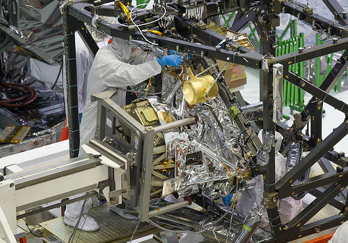
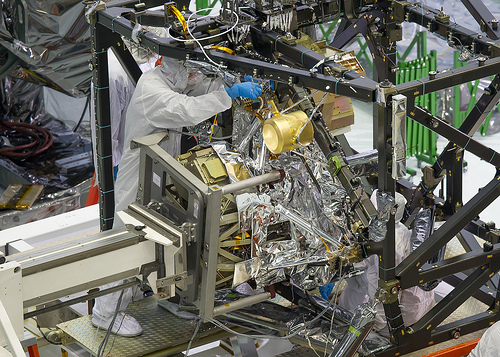
A technician is installing the bolts that will hold the MIRI, or Mid-Infrared Instrument, to the composite Integrated Science Instrument Module (ISIM) structure, or the black frame. The MIRI is attached to a balance beam, known as the Horizontal Integration Tool (HIT), hanging from a precision overhead crane. That is the identical tool that Hubble engineers employed to prepare hardware for its servicing missions.

Photo Credit: NASA/Chris Gunn Text Credit: NASA/Laura Betz

—-

Engineers worked meticulously to implant the James Webb Space Telescope’s Mid-Infrared Instrument into the ISIM, or Integrated Science Instrument Module, in the cleanroom at NASA’s Goddard Space Flight Center in Greenbelt, Md. As the successor to NASA’s Hubble Space Telescope, the Webb telescope will be the most strong space telescope ever constructed. It will observe the most distant objects in the universe, offer pictures of the very first galaxies formed and see unexplored planets about distant stars.

For far more details, visit: www.jwst.nasa.gov

NASA image use policy.

NASA Goddard Space Flight Center enables NASA’s mission by way of 4 scientific endeavors: Earth Science, Heliophysics, Solar Technique Exploration, and Astrophysics. Goddard plays a top role in NASA’s accomplishments by contributing compelling scientific information to advance the Agency’s mission.

Adhere to us on Twitter

Like us on Facebook

Discover us on Instagram

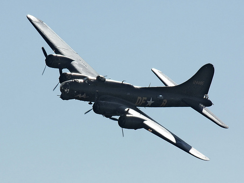
Boeing B-17 – Duxford Airshow Oct 2010
precision engineering services
Image by Feggy Art
Boeing B-17 at Duxford Airshow October 2010.

The Boeing B-17 Flying Fortress was a four-engine heavy bomber aircraft created in the 1930s for the United States Army Air Corps (USAAC). Competing against Douglas and Martin for a contract to develop 200 bombers, the Boeing entry outperformed each competitors and more than met the Air Corps’ expectations. Despite the fact that Boeing lost the contract simply because the prototype crashed, the Air Corps was so impressed with Boeing’s design that they ordered 13 a lot more B-17s for additional evaluation. From its introduction in 1938, the B-17 Flying Fortress evolved by way of quite a few design advances.

The B-17 was mostly employed by the United States Army Air Forces (USAAF) in the daylight precision strategic bombing campaign of Planet War II against German industrial and military targets. The United States Eighth Air Force primarily based at Thorpe Abbotts airfield in England and the Fifteenth Air Force primarily based in Italy complemented the RAF Bomber Command’s night time area bombing in Operation Pointblank to assist safe air superiority over the cities, factories and battlefields of Western Europe in preparation for Operation Overlord. The B-17 also participated to a lesser extent in the War in the Pacific exactly where it carried out raids against Japanese shipping and airfields.

From its pre-war inception, the USAAC (later USAAF) touted the aircraft as a strategic weapon it was a potent, higher-flying, long-variety bomber that was capable to defend itself, and to return house in spite of in depth battle harm. It swiftly took on mythic proportions, and extensively circulated stories and photographs of B-17s surviving battle harm enhanced its iconic status. With a service ceiling higher than any of its Allied contemporaries, the B-17 established itself as an efficient weapons technique, dropping far more bombs than any other U.S. aircraft in World War II. Of the 1.five million metric tons of bombs dropped on Germany by U.S. aircraft, 640,000 tons have been dropped from B-17s.

General characteristics

•Crew: 10: Pilot, co-pilot, navigator, bombardier/nose gunner, flight engineer-leading turret gunner, radio operator, waist gunners (2), ball turret gunner, tail gunner
•Length: 74 ft 4 in (22.66 m)
•Wingspan: 103 ft 9 in (31.62 m)
•Height: 19 ft 1 in (five.82 m)
•Wing region: 1,420 sq ft (131.92 m2)
•Airfoil: NACA 0018 / NACA 0010
•Aspect ratio: 7.57
•Empty weight: 36,135 lb (16,391 kg)
•Loaded weight: 54,000 lb (24,500 kg)
•Max takeoff weight: 65,500 lb (29,700 kg)
•Powerplant: 4× Wright R-1820-97 Cyclone turbo supercharged radial engines, 1,200 hp (895 kW) each and every

Functionality

•Maximum speed: 287 mph (249 kn, 462 km/h)
•Cruise speed: 182 mph (158 kn, 293 km/h)
•Range: 2,000 mi (1,738 nmi, 3,219 km) with two,700 kg (6,000 lb) bombload
•Service ceiling: 35,600 ft (ten,850 m)
•Rate of climb: 900 ft/min (4.6 m/s)
•Wing loading: 38. lb/sq ft (185.7 kg/m2)
•Power/mass: .089 hp/lb (150 W/kg)

Armament

•Guns: 13 × .50 in (12.7 mm) M2 Browning machine guns in four turrets in dorsal, ventral, nose and tail, 2 in waist positions, 2 beside cockpit and 1 in the reduced dorsal position
•Bombs:
•Short variety missions (&lt400 mi): 8,000 lb (three,600 kg)
•Long variety missions (≈800 mi): 4,500 lb (2,000 kg)
•Overload: 17,600 lb (7,800 kg)

Text and specifications primarily based on Wikipedia write-up beneath the Inventive Commons License for non-profit use.

This is the Boeing B17G-105-VE Flying Fortress 124485 G-BEDF (Memphis Belle)

Cool Milling Engineering photos

Cool Milling Engineering photos

Some cool milling engineering images:

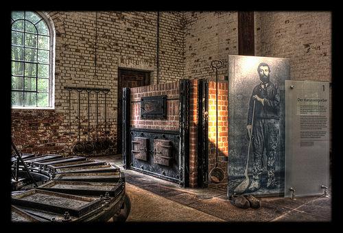
Hagen – Freilichtmuseum Hagen – Zink Walzwerk Karusellgießer Fa. Hoesch
milling engineering
Image by Daniel Mennerich
The Hagen Open-air Museum (LWL-Freilichtmuseum Hagen – Westfälisches Landesmuseum für Handwerk und Technik English: &quotLWL Open-air Museum Hagen – Westphalian State Museum for Craft and Technics&quot) is a museum at Hagen in the southeastern Ruhr area, North Rhine-Westphalia, Germany. It was founded, collectively with the Detmold Open-air Museum, in 1960, and was very first opened to the public in the early 1970s. The museum is run by the Landschaftsverband Westfalen-Lippe (LWL, regional authority for Westphalia and Lippe inside North Rhine-Westphalia). It lies in the Hagen neighbourhood of Selbecke south of Eilpe in the Mäckingerbach valley.

The open-air museum brings a bit of skilled-trade history into the present, and it takes a hands-on approach. On its grounds stretching for about 42 ha, not only are urban and rural trades basically &quotdisplayed&quot along with their workshops and tools, but in a lot more than twenty of the almost sixty rebuilt workshops, they are nonetheless practised, and interested guests can, often by themselves, take part in the production.

As early as the 1920s, there have been efforts by a group of engineers and historical preservationists to preserve technological monuments for posterity. The initiator, Wilhelm Claas, even recommended the Mäckingerbach valley as a good location for a museum to that end. The narrow valley was chosen, as wind, water and wood had been the 3 most crucial place factors for industry in the 18th and 19th centuries.

In 1960, the Westphalian Open-Air Museum was founded, and thirteen years later, the gates opened to the public. Unlike most open-air museums, which show each day life on the farm or in the nation as it was in days gone by, the Hagen Open-Air Museum puts the history of these activities in Westphalia in the fore. From the late 18th century by means of the early years of the Industrial Revolution to the hugely industrialized society emerging in the early 20th century, the visitor can experience the development of these trades and the business in the area.

Crafts and trades demonstrated at the Westphalian Open-Air Museum contain ropemaking, smithing, brewing, baking, tanning, printing, milling, papermaking, and much a lot more. A favourite attraction is the triphammer workshop shown in the image above. As soon as the hammer is engaged, a craftsman goes to perform noisily forging a scythe, passing it in between the hammer and the anvil underneath in a procedure named peening.

The Hagen Westphalian Open-Air Museum is open from March or April until October.

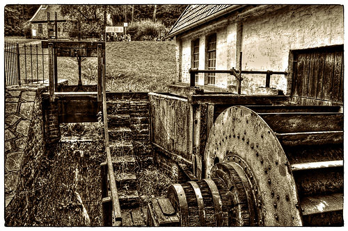
Hagen – Freilichtmuseum Hagen – Sensenschmiede 07
milling engineering
Image by Daniel Mennerich
The Hagen Open-air Museum (LWL-Freilichtmuseum Hagen – Westfälisches Landesmuseum für Handwerk und Technik English: &quotLWL Open-air Museum Hagen – Westphalian State Museum for Craft and Technics&quot) is a museum at Hagen in the southeastern Ruhr region, North Rhine-Westphalia, Germany. It was founded, together with the Detmold Open-air Museum, in 1960, and was first opened to the public in the early 1970s. The museum is run by the Landschaftsverband Westfalen-Lippe (LWL, regional authority for Westphalia and Lippe within North Rhine-Westphalia). It lies in the Hagen neighbourhood of Selbecke south of Eilpe in the Mäckingerbach valley.

The open-air museum brings a bit of skilled-trade history into the present, and it takes a hands-on approach. On its grounds stretching for about 42 ha, not only are urban and rural trades just &quotdisplayed&quot along with their workshops and tools, but in much more than twenty of the nearly sixty rebuilt workshops, they are nevertheless practised, and interested visitors can, occasionally by themselves, take component in the production.

As early as the 1920s, there were efforts by a group of engineers and historical preservationists to preserve technological monuments for posterity. The initiator, Wilhelm Claas, even suggested the Mäckingerbach valley as a very good location for a museum to that end. The narrow valley was selected, as wind, water and wood were the 3 most important place variables for market in the 18th and 19th centuries.

In 1960, the Westphalian Open-Air Museum was founded, and thirteen years later, the gates opened to the public. In contrast to most open-air museums, which show each day life on the farm or in the country as it was in days gone by, the Hagen Open-Air Museum puts the history of these activities in Westphalia in the fore. From the late 18th century by way of the early years of the Industrial Revolution to the very industrialized society emerging in the early 20th century, the visitor can encounter the development of these trades and the industry in the region.

Crafts and trades demonstrated at the Westphalian Open-Air Museum incorporate ropemaking, smithing, brewing, baking, tanning, printing, milling, papermaking, and significantly much more. A favourite attraction is the triphammer workshop shown in the image above. As soon as the hammer is engaged, a craftsman goes to function noisily forging a scythe, passing it amongst the hammer and the anvil underneath in a method known as peening.

The Hagen Westphalian Open-Air Museum is open from March or April until October.

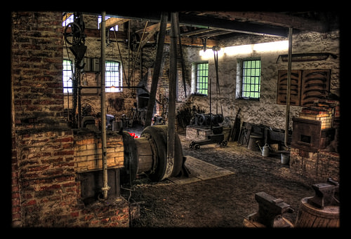
Hagen – Freilichtmuseum Hagen – Sensenschmiede 04
milling engineering
Image by Daniel Mennerich
The Hagen Open-air Museum (LWL-Freilichtmuseum Hagen – Westfälisches Landesmuseum für Handwerk und Technik English: &quotLWL Open-air Museum Hagen – Westphalian State Museum for Craft and Technics&quot) is a museum at Hagen in the southeastern Ruhr location, North Rhine-Westphalia, Germany. It was founded, collectively with the Detmold Open-air Museum, in 1960, and was first opened to the public in the early 1970s. The museum is run by the Landschaftsverband Westfalen-Lippe (LWL, regional authority for Westphalia and Lippe within North Rhine-Westphalia). It lies in the Hagen neighbourhood of Selbecke south of Eilpe in the Mäckingerbach valley.

The open-air museum brings a bit of skilled-trade history into the present, and it requires a hands-on strategy. On its grounds stretching for about 42 ha, not only are urban and rural trades basically &quotdisplayed&quot along with their workshops and tools, but in a lot more than twenty of the nearly sixty rebuilt workshops, they are nonetheless practised, and interested visitors can, at times by themselves, take portion in the production.

As early as the 1920s, there have been efforts by a group of engineers and historical preservationists to preserve technological monuments for posterity. The initiator, Wilhelm Claas, even suggested the Mäckingerbach valley as a good place for a museum to that finish. The narrow valley was selected, as wind, water and wood had been the 3 most critical place factors for market in the 18th and 19th centuries.

In 1960, the Westphalian Open-Air Museum was founded, and thirteen years later, the gates opened to the public. In contrast to most open-air museums, which show everyday life on the farm or in the country as it was in days gone by, the Hagen Open-Air Museum puts the history of these activities in Westphalia in the fore. From the late 18th century by way of the early years of the Industrial Revolution to the highly industrialized society emerging in the early 20th century, the visitor can knowledge the development of these trades and the sector in the region.

Crafts and trades demonstrated at the Westphalian Open-Air Museum contain ropemaking, smithing, brewing, baking, tanning, printing, milling, papermaking, and considerably much more. A favourite attraction is the triphammer workshop shown in the image above. Once the hammer is engaged, a craftsman goes to function noisily forging a scythe, passing it amongst the hammer and the anvil underneath in a procedure named peening.

The Hagen Westphalian Open-Air Museum is open from March or April until October.