Cool Prototype Engineering photos

Cool Prototype Engineering photos

A handful of good prototype engineering images I located:

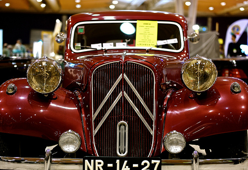
Citroen 7 CV
prototype engineering
Image by pedrosimoes7
MotorClássico, Lisbon, Portugal

in Wikipedia

Traction Avant monocoque

Front torsion bar suspension

The Traction Avant, French for &quotfront wheel drive&quot, was made by André Lefèbvre and Flaminio Bertoni in late 1933 / early 1934. Although not the initial production front wheel drive car – Alvis constructed the 1928 FWD in the UK, Cord made the L29 from 1929 to 1932 in the United States and DKW the F1 in 1931 in Germany – it was the world’s initial front-wheel drive steel monocoque production vehicle. Along with DKW’s 1930s models, the Traction effectively pioneered front-wheel drive on the European mass automobile market place.

The Traction Avant’s structure was a welded monocoque (unitized physique). Most other vehicles of the era had been based on a separate frame (chassis) onto which the non-structural body (&quotcoachwork&quot) was built. Monocoque building (also called Unit Physique or &quotUnibody&quot in the US nowadays) benefits in a lighter car, and is now employed for virtually all vehicle building, even though body-on-frame building remains appropriate for bigger autos such as trucks.
This method of construction was viewed with wonderful suspicion in many quarters, with doubts about its strength. A sort of crash test was conceived, taking the type of driving the auto off a cliff, to illustrate its wonderful inherent resilience.

The novel design and style created the car really low-slung relative to its contemporaries – the Traction Avant usually possessed a distinctive appear, which went from appearing rakish in 1934 to familiar and somewhat old fashioned by 1955.

The suspension was really sophisticated for the car’s era. The front wheels were independently sprung, using a torsion bar and wishbone suspension arrangement,[3] where most contemporaries utilised live axle and cart-sort leaf spring styles. The rear suspension was a easy steel beam axle and a Panhard rod, trailing arms and torsion bars attached to a 3-inch (76 mm) steel tube, which in turn was bolted to the monocoque.

Because it was significantly lighter than traditional styles of the era, it was capable of one hundred km/h (62 mph), and consumed fuel only at the rate of ten litres per one hundred kilometres (28 mpg-imp 24 mpg-US).

Variants

Cabriolet

Traction Avant rear

1937 7C Coupe Traction Avant

A French &quotfamiliale&quot 11 F 1954, six windows, 9 seats

Citroën 11 Commerciale five-door

Traction Avant rears. The boot was lengthened and its volume doubled in Autumn 1952.[four]
The original model, which was presented on 18 April 1934, was a tiny saloon with a 1,303 cc (79.five cu in) engine. This model was known as the 7A, which was succeeded in June 1934 by the 7B with a higher-power engine of 1,529 cc (93.3 cu in). The 7B in turn, was succeeded in October 1934 by the 7C with an even greater-output 1,628 cc (99.3 cu in) engine. Later models have been the 11 (launched in November 1934), which had a 1,911 cc (116.six cu in) four-cylinder engine, and the 15 (launched in 1938), with a two,867 cc (175. cu in) six. The numbers refer to the French fiscal horsepower rating, or CV. The 11 was an 11 CV, but curiously the 15 was truly 16 CV. The 11 was constructed in two versions, the 11L (&quotlégère&quot, or &quotlight&quot), which was the identical size as the 7 CV, and the normal model 11, which had a longer wheelbase and wider track.

Citroën planned two variants that by no means entered production, given that there was not enough funding available to develop them, except as running prototype automobiles. 1 was an automatic transmission-equipped model, based on the Sensaud de Lavaud automatic transmission, the other a 22 CV model with a three.8 liter V8. The transmission (which was really initially created for the Citroen) was a &quotgearless&quot automatic, employing the torque-converter alone to match engine revolutions to the drivetrain revolutions, significantly like the Dynaflow Transmission introduced later in the USA. The vehicle was supposed to have a much less spartan interior than the other Traction Avants and it was to function Citroën’s own new V8 engine. About twenty prototypes have been produced, but when the project was canceled in 1935 due to Michelin’s takeover they were most likely all destroyed.[citation required]

In addition to the 4-door physique, the auto was also produced as a two-door coupé with a rumble seat, as a convertible and as an extended length Familial model with 3 rows of seats. There was even a hatchback-kind Commerciale variant, in 1939, well ahead of its time, in which the tailgate was in two halves, the reduced of which carried the spare wheel with the upper opening up to roof level. A one-piece leading-hinged tailgate was introduced when the Commerciale resumed production in 1954 soon after being suspended during World War II.
Wartime disruption[edit]

In September 1939 France declared war on Germany and in June 1940 the German army quickly invaded and occupied Northern France.[1] The war years were characterised by a desperate shortage of raw components for civilian market and of petrol,[1] but these variables have been not apparent quickly. The Paris Motor Show scheduled for October 1939 was cancelled at quick notice, but Citroën’s personal planned announcements had involved the forthcoming 2CV model rather than any significant adjustments to the Traction.[1] For the Traction, the final “normal” year in terms of production levels was 1939, and eight,120 of the 2910mm wheelbase 1628cc engined 7C models have been developed.[1] This tumbled to 1,133 in 1940, which was the initial year when the plant suffered severe air-raid damage – on this occasion caused by a German attack – on three June 1940. Production of the vehicles was suspended in June 1941, by when a further 154 had been produced in the six-month period just ended. The 7C would continue to seem in Citroën price-lists until March 1944, but production of this smaller engined “7CV” version of the Traction was not resumed soon after the war.[1] For the a lot more powerful 1911cc engined 11 B-light models, the equivalent figures were 27,473 units created in 1939, 4,415 in 1940 and two,032 for 1941, even though for this model production in 1941 ended only in November 1941 so the figure for that year represents 11 months of production.[1]

In 1945 production restarted only slowly: the 11 B-light reappeared really tiny changed from the 1941 automobiles except that headlight surrounds were now painted rather than finished in chrome. By the end of December 1945 the year’s production had reached 1,525.[1] Currency depreciation is evident from the car’s listed cost which had been 26,800 francs in January 1940, and had risen to 110,670 francs in October 1945.[1] In 1945 the auto was the only model accessible from Citroën, and as one more sign of the instances, customers not in a position to supply their own tires were charged an extra 9,455 francs for a set of five.[1] In May possibly 1946, presumably reflecting an easing of the war-time tire shortage, the auto could at last be bought with tires at no added cost, but by now the all round price tag of an 11 B-light had risen to 121,180 francs.[1]

The 11 B-normal model, differentiated from the 11 B-light by its 3090mm wheelbase, knowledgeable a comparable drop off in volumes between 1939 and 1941, with just 341 cars produced for the duration of the first seven months of 1941.[1] Right after the war, a single 11 B-normal was developed in 1946, in time to be presented at the October 1946 Paris Motor Show: production constructed up throughout 1947, but for the duration of the car’s ten-year post-war period the shorter 11 B-light would, in France, continue to outsell the 11 B-normal.

Initially the French army lacked enthusiasm for the Citroën Traction, believing that it presented insufficient ground-clearance for their needs.[1] Nonetheless, by September 1939 roughly 250 had found their way into military service. With losses of automobiles at the frontier mounting, Citroën supplied a further 570 to the army in between February and Could 1940, and subsequent deliveries almost certainly took location just before military defeat intervened.[1] In the course of the war many of the automobiles were reregistered with &quotWH…&quot (Wehrmacht Heer/Army command) license plates, obtaining been requisitioned by the German Army.[1] These gave reliable service each in France and further afield, notably in Libya and Stalingrad. Tractions have been also favoured by the Resistance, and as occupation gave way to Liberation they turned up all more than France with FFI inscribed proudly on their doors. Less gloriously, the automobiles were identified as favourites among gangsters such as the then infamous Pierrot le Fou, and his Traction gang.

UK built automobiles[edit]

Left-hand drive versions had been built in Paris, in Forest, Belgium, in Copenhagen, Denmark for the Scandinavian market place, and correct-hand drive cars in Slough, England. The Slough version of the 11L was named the Light Fifteen and the long wheelbase 11 was referred to as the Large Fifteen. This confusing terminology referred to the British fiscal tax rating of the time, which was greater than the French, so the 11CV engine was 15HP in England. The 15CV model was known as &quotBig Six&quot in reference to its six-cylinder engine. They have been equipped with the leather seats and wooden dashboards popular in the UK, had a 12-volt electrical method and had been distinguished by a diverse radiator grille and distinct bumpers. Some models also had a sliding sunroof.
A 1,911 cc (116.six cu in) Light Fifteen tested by the British magazine The Motor in 1951 had a leading speed of 72.6 mph (116.eight km/h) and could accelerate from 0–60 mph (97 km/h) in 29.7 seconds. A fuel consumption of 25.two miles per imperial gallon (11.2 L/one hundred km 21. mpg-US) was recorded. The test car cost GB£812 including taxes.[five]

A two,866 cc (174.9 cu in) six-cylinder model was tested by the very same magazine in 1954 and for this vehicle the best speed found was 81.1 mph (130.five km/h), acceleration from 0–60 mph (97 km/h) 21.2 seconds and fuel consumption 18.six miles per imperial gallon (15.two L/100 km 15.five mpg-US). The test vehicle expense GB£1,349 like taxes.[six]
Engineering[edit]

Citroën 11 CV Légère

The Traction Avant used a longitudinal, front-wheel drive layout, with the engine set effectively within the wheelbase, resulting in a really favourable weight distribution, aiding the car’s sophisticated handling qualities. The gearbox was placed at the front of the automobile with the engine behind it and the differential among them, a layout shared with the later Renault four and 16 and initial generation Renault five but the opposite way round to numerous longitudinal front-wheel drive vehicles, such as the Saab 96 and Renault 12 and 18 and most Audi models. The gear alter was set in the dashboard, with the lever protruding through a vertical, H-shaped gate.[7] Due to the fact this vertical orientation could have resulted in the auto dropping out of gear when the lever was in the upper positions (i.e., second or reverse gears), the gear shift mechanism was locked when the mechanical clutch was engaged and released when the clutch pedal was depressed. The outcome of this layout, along with pendant pedals, umbrella-sort handbrake handle and front bench seats, was a very spacious interior, with a flat and unobstructed floor. The low-slung arrangement also eliminated the want for running boards to step into or out of the car. These features created them ideal for use as limousines and taxi cabs, and they were quite well-known among drivers and passengers alike. Until 1953, black was the only color offered.

Effect on Motorsport[edit]

Another technical significance of Tranction Avant was the cast aluminium alloy transaxle, which was pioneered by Hans Ledwinka in the early 1930s for Tatra V570 utilised in front of the engine positioned in the rear, but was really radical at the time.

As well as being a considerable component of the weight savings, the manufacturing facility for this transaxle contributed to the under talked about financial crisis. But when John Cooper looked for a light transaxle case for Formula 1 rear engine revolution, Traction Avant unit was about the only candidate, as Volkswagen magnesium alloy transaxle was a lot smaller and lacking the space needed to property heftier gears needed for Formula 1. The Traction Avant transaxle was utilised on Cooper T43 which won a F1 championship race as the very first mid-mounted engine automobile to do so in 1958, and on its successors Cooper T45, T51 and T53. Cooper T51 won the GP World Championship in 1959.

Unlike the Volkswagen alloy case used by Hewland, the Traction Avant case could not be utilized up side down, as the input shaft height was much larger in relation to the output shaft axis so that the oil level needed to lubricate the gears would exceed the then-unreliable input shaft oil seal height if employed upside down. So the engine necessary to sit higher above the ground with the oil sump space beneath, which was not necessary by dry-sump racing engines. But the French transaxle was used by numerous racing automobile constructors in the late 1950s to 60’s with various levels of success.

In the case of Jack Brabham, who personally visited the ERSA foundry in Paris to discuss a possibility to strengthen the case ,[eight] the transaxle became known as &quotERSA Knight&quot with an further spur-gear set mounted in the bellhousing spacer (engine to transaxle adapter) recommended by Ron Tauranac, named for Jack Knight who designed the modification and produced the straight-reduce gears. The height offset produced by the spur gear set enabled the engine to sit lower, and became the reason why Cooper T53 was known as the ‘Lowline’, which not only made Brabham the World Champion in 1960 but also became the precursor to the establishment of Brabham as a Formula A single constructor.

Effect on Citroën[edit]

1954 six-cylinder 15CV with hydropneumatic suspension fitted to the rear wheels – in ‘high’ position

Traction Avant as modern wedding car

The development charges of the Traction Avant, combined with the redevelopment of its factory, had been extremely high and Citroën declared bankruptcy in late 1934. The biggest creditor was Michelin, who then owned Citroën from 1934 till 1976. Beneath Michelin, Citroën was run as a study laboratory, a test bed for their radial tires and new automotive technologies.
In 1954 Citroën’s experiments with hydropneumatic technologies produced its first result, the &quot15H&quot – a variant of the 6-cylinder model 15 with a self-leveling, height-adjustable rear suspension, a field trial for the revolutionary DS released the following year.

Directly soon after the introduction of the Citroën ID, a simplified and much more competitively priced version of the nonetheless revolutionary DS, production of the Traction Avant ended in July 1957. Over 23 years, 759,111 had been built, such as 26,400 assembled in Slough in England, 31,750 assembled in Forest near Brussels and 1,823 assembled at Cologne in Germany. The total reflects the production stoppage for the duration of World War II.

The Traction Avant nowadays[edit]

Big Fifteen sedan

In 2006, the oldest surviving 7A has production quantity (&quotcoque nr&quot) AZ 00-18, and is displayed in partly dismantled shape (engine and front wheels detached) in the Citroën Museum in Paris. The oldest operating 7A is possibly number AZ-00-23, which was, till 1 September 2006, in possession of a Dutch owner and is now with a Slovenian owner.
Traction Avants are fairly robust autos even by contemporary requirements nevertheless, they are prone to leaking water inside the cabin and care requirements to be taken when acquiring one. Each few years, Traction Avant enthusiasts ship their autos to an exotic location for a rally. In 2002, for example, a group of more than 30 Traction Avants drove from Los Angeles to New York with no incident. [1]

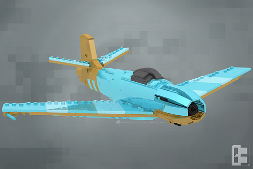
G-92 “Krut” Jet Fighter
prototype engineering
Image by Backward Matt
For also lengthy the engineers of the Kingdom’s navy laughed at the engineers of the air force, and for excellent purpose the Sky Ram produced by Meloa Industries was a disastrous tiny plane and paled in comparison to the Neustrasian’s Maelstrom supply.

But no more soon after the -ahem- &quotperfectly legal&quot &quotacquisition&quot of the subsequent generation jet engine prototype developed by the MURICANs, a secret project was contracted with Piccolo Aircraft. The majority of Meloa Industries personnel left to make naval versions of the Maelstrom for the major naval designers, but a handful of crazy, stubborn determined people joined the struggling engineers of Neustrasia’s Mayenne and a Georgian firm, founding Piccolo Aircraft which worked beneath the radar (literally, in some situations) to create the Piccolo G-92 &quotKrut&quot to outdo all other jet fighters ever created up to that point. After 92 diverse design and style prototypes (most of them dying as wooden models in air tunnels) primarily based of the Manchot, Direwolf and possibly a handful of stolen Germanikan fighters, the design and style team went through forty six pounds of coffee beans, five of some of Neustrasia’s best pilots, a few water blessings to purge demon spirits, and a certain wealthy man’s life savings going to charity after losing a bet the fighter flies, and it flies nicely! So properly, in truth, that many of its elements are classified. :^)

Also, unknown to most of the globe, but very perplexing to the military leaders of Neustrasia, all their ideal pilots not already out for active duty were mysteriously re-assigned. This is why the ideal pilots of Terra get to fly the greatest fighter of Terra. 8^)

Note that all of that rambling is flavor text for the fictional universe of D&ampC IV, which is set in an alternate 1947.

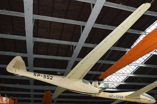
IS-1 Sęp bis ‘SP-552’
prototype engineering
Image by Hawkeye UK
c/n 011.
On show suspended in the major show hangar at the Muzeum Lotnictwa Polskiego
Krakow, Poland.
23-08-2013.

The following information is taken from the museum internet site:-

&quotThis is a single seater, all wooden, higher functionality glider of a higher wing cantilever configuration. The wings are equipped with divided flaperons, flaps, aerodynamic brakes and interceptors. In 1945, the group of gliding enthusiasts decided to re-activate the Silesian Glider Workshops, which had been established ahead of the Second World War. As a outcome of this initiative, the Gliding Institute was established in 1946. Its objective was to design and style new gliders, utilizing Polish encounter in this field.
The Sęp (vulture) was the very first after-war Polish building made at the Gliding Institute in Bielsko Biała. The initial style was carried our by engineers: Józef Niespał and Władysław Nowakowski. Despite hard occasions the prototype was flown on 2nd June 1947and currently in July of the very same year, the Sęp flown by Adam Ziętek represented Poland on the International Gliders Competitors in Samedan, Switzerland. It came eight. The Polish glider was the only new construction there. The other participants flew the pre-war or the captured German gliders To the subsequent examples a few minor adjustments (in the wings building and the cockpit equipment) have been introduced. The modified version bore the &quotSęp bis&quot designation.
The total production quantity (collectively with prototypes) was six gliders, the last 1 was nonetheless flying at the starting of 1960’s Flying the Sęps, the Polish glider pilots set many domestic and planet records.
The IS-1 Sęp bis, displayed, bearing the SP-552 markings, was in service from 1948 till 1960, and took part in several different championships. In 1949, Irena Kempówna established two speed records. In 1964, the glider was handed over to the museum.&quot

Cool High Precision Engineering pictures

Cool High Precision Engineering pictures

A handful of nice higher precision engineering photos I found:

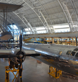
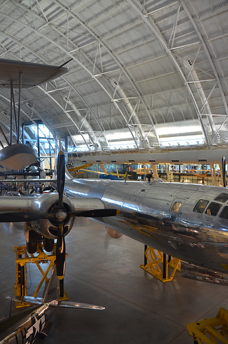
Steven F. Udvar-Hazy Center: south hangar panorama, including Vought OS2U-3 Kingfisher seaplane, B-29 Superfortress “Enola Gay”, among other people
high precision engineering
Image by Chris Devers
Quoting Smithsonian National Air and Space Museum | Vought OS2U-3 Kingfisher:

The Kingfisher was the U.S. Navy’s main ship-primarily based, scout and observation aircraft for the duration of World War II. Revolutionary spot welding strategies gave it a smooth, non-buckling fuselage structure. Deflector plate flaps that hung from the wing’s trailing edge and spoiler-augmented ailerons functioned like additional flaps to permit slower landing speeds. Most OS2Us operated in the Pacific, where they rescued numerous downed airmen, like World War I ace Eddie Rickenbacker and the crew of his B-17 Flying Fortress.

In March 1942, this airplane was assigned to the battleship USS Indiana. It later underwent a six-month overhaul in California, returned to Pearl Harbor, and rejoined the Indiana in March 1944. Lt. j.g. Rollin M. Batten Jr. was awarded the Navy Cross for generating a daring rescue in this airplane below heavy enemy fire on July four, 1944.

Transferred from the United States Navy.

Manufacturer:
Vought-Sikorsky Aircraft Division

Date:
1937

Country of Origin:
United States of America

Dimensions:
General: 15ft 1 1/8in. x 33ft 9 1/2in., 4122.6lb., 36ft 1 1/16in. (460 x 1030cm, 1870kg, 1100cm)

Components:
Wings covered with fabric aft of the primary spar

Physical Description:
Two-seat monoplane, deflector plate flaps hung from the trailing edge of the wing, ailerons drooped at low airspeeds to function like further flaps, spoilers.

• • • • •

Quoting Smithsonian National Air and Space Museum | Boeing B-29 Superfortress &quotEnola Gay&quot:

Boeing’s B-29 Superfortress was the most sophisticated propeller-driven bomber of Planet War II and the first bomber to property its crew in pressurized compartments. Though created to fight in the European theater, the B-29 discovered its niche on the other side of the globe. In the Pacific, B-29s delivered a variety of aerial weapons: traditional bombs, incendiary bombs, mines, and two nuclear weapons.

On August 6, 1945, this Martin-constructed B-29-45-MO dropped the very first atomic weapon used in combat on Hiroshima, Japan. Three days later, Bockscar (on display at the U.S. Air Force Museum close to Dayton, Ohio) dropped a second atomic bomb on Nagasaki, Japan. Enola Gay flew as the advance weather reconnaissance aircraft that day. A third B-29, The Wonderful Artiste, flew as an observation aircraft on both missions.

Transferred from the United States Air Force.

Manufacturer:
Boeing Aircraft Co.
Martin Co., Omaha, Nebr.

Date:
1945

Nation of Origin:
United States of America

Dimensions:
All round: 900 x 3020cm, 32580kg, 4300cm (29ft 6 5/16in. x 99ft 1in., 71825.9lb., 141ft 15/16in.)

Materials:
Polished general aluminum finish

Physical Description:
Four-engine heavy bomber with semi-monoqoque fuselage and high-aspect ratio wings. Polished aluminum finish all round, common late-Planet War II Army Air Forces insignia on wings and aft fuselage and serial quantity on vertical fin 509th Composite Group markings painted in black &quotEnola Gay&quot in black, block letters on lower left nose.

Cool Sheet Metal Components China pictures

Cool Sheet Metal Components China pictures

Verify out these sheet metal parts china photos:

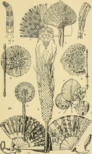
Image from page 429 of “Handbook of ornament a grammar of art, industrial and architectural designing in all its branches, for sensible as effectively as theoretical use” (1900)
sheet metal parts china
Image by Internet Archive Book Pictures
Identifier: handbookoforname1900meye
Title: Handbook of ornament a grammar of art, industrial and architectural designing in all its branches, for practical as effectively as theoretical use
Year: 1900 (1900s)
Authors: Meyer, Franz Sales, 1849-
Subjects: Decoration and ornament Art objects
Publisher: New York, B. Hessling
Contributing Library: Wellesley College Library
Digitizing Sponsor: Wellesley College Library

View Book Page: Book Viewer
About This Book: Catalog Entry
View All Pictures: All Photos From Book

Click here to view book on the web to see this illustration in context in a browseable on the web version of this book.

Text Appearing Prior to Image:
ne end by a pin, which serves asthe axis. They are collapsible into a narrow shape, andmay be opened-out to a semi-circle. They are held-togetherby a ribbon drawn by way of them (fig. 13). five. The Folding fan: distinguished from the preceding by thelamellae getting covered by a sheet of paper, silk, &ampc., whichis folded – together or spread-out by the opening of the stickswhich compose the frame (fig. 14). It appears from this that the Fixed, the Pennon, and the Radialfans have handles, although the Lamellar and the Folding fans have not.The Radial fan, being a folding fan with a handle, is a sort of inter-mediate form. The size of the fan varies according to style andthe goal for which it is intended, regard getting normally paid toconvenience of handling as a general rule, it could be said that thefirmer, stiffer and a lot more impervious to air the fan is: the smaller itmay be. Fans for cooling need to have a quick, broad type, Fly-flappers demand a longer, narrower shape. METAL OBJECTS. 415

Text Appearing Right after Image:
The Fan. Plate 289. 416 The Fan. On the topic of history and style, the following may possibly be mentioned:The Fixed fan is the oldest and most primitive. Its organic model isa leaf on a stalk, just as savages at the present time make their fansof dried palm-leaves or of plaited perform in the kind of leaves (fig. 4).The feather might also be regarded as a organic model, and therefore itsfrequent application to fans of each type. The Pennon fan is theleast sensible, its domain is the Middle Ages and the early Eenascence,with each other with particular parts of the East (India, Turkey, Morocco,Tunis, &ampc.). The Eadial fan was also in use in the Middle ages (witha long handle), and down to the present time in particular parts of Italy,Persia, China, and Japan. The Lamellar and the Folding fan are oflater date. Their introduction is contemporaneous with the generaluse of the fan in Europe (15 th century). Right after the period of thelamellar fan in the 17 th century, follows the golden age of the foldingfan in the Rococ

Note About Images
Please note that these photos are extracted from scanned page pictures that could have been digitally enhanced for readability – coloration and look of these illustrations may not completely resemble the original perform.

Cool Fast Prototyping images

Check out these fast prototyping images:

PSX
fast prototyping
Image by JulianBleecker
The prototype test rig here. It turns out this is _so_ overengineered my head’s going to explode. Why? What the heck happened?

Well, I think I got way too far ahead of myself and designed the circuit before looking closely at the technical problem I was trying to solve. I was a bit eager to create a little interaction ritual and was thinking quite hard about the implications a peculiar kind of game controller like this would have on my playing the game Katmari Damacy. I was thinking so hard about that side of the problem and not even bothering (over the summer) to look at my PS2 and figure out what the electrical signals were doing — or even prototyping on this STK500 development kit I have. I went ahead and designed a circuit, laid out a printed circuit board, and had the board manufactured, mostly because I was excited that I could.

Now I have an over-engineered board where half the stuff on it probably won’t be used!

Sigh..

Oh well. Lesson learned.

What did I learn?

For this particular project, social engineering — creating new kinds of interaction rituals — cannot ignore electrical engineering. The two need to happen simulatneously. I should have been as engaged in studying the electrical parameters of the problem as I was in studying and reading-up on the social engineering aspects. What is the social engineering? Investigating how social practice is shaped by the affordances we are given for engaging in interactions. In this case, the interactions we have with the imaginary logic of this particular game — Katmari Damacy — can be shaped and extended by a device that extends the material aspects of the game into an "offline" experience. How will my imagination of the game shift when I have to do things away from the television screen and video game console as an aspect of the game mechanic?

The electrical engineering — what got over-engineered — could have been made short, sweet and quite modest in its design had I studied the problem a bit more, and had more discussions about what I was doing. As it is, my harvesting of other people’s projects did not go far enough. I found plenty of information about how to connect a PSX game controller to "other things" (like microcontrollers), I came up short on information about making a PS2 console think some "other thing" (like a microcontroller) was a PSX game controller. In other words — spoofing a PS2 console. I guess my Google search parameters were off, but also I just blindly assumed that if I could understand how to talk to a controller, the inverse would be simple. In fact, the inverse is simple — there’s nothing left to learn, really, except that I neglected to consider that the PS2 console fairly well blazes along. Interacting with a controller can happen as slow as you want, whereas the PS2 console wants to make things happen quite fast. So fast, in fact, that the code I had written was missing the beat, effectively. As I had designed things in "bit-banged" mode, I just figured I could pretty much manually communicate with the console, but things happen quite fast, and doing things like using interrupts and such — well, the code couldn’t get into the service routine quickly enough to respond to 2us clock pulses, so then you’re in a situation of "dead reckoning" to find clocks and such. It started to feel a bit krufty — a bit messy.

Pinging todbot helped me to look at using the built-in serial communication hardware found on the Atmel microcontroller, and in short order he had emailed me links I wish I had found two months ago — other folks using 3-wire (SPI) interfaces to do precisely the engineering I was trying to do.

On to prototype number 2.

Cool Sheet Metal Parts China images

Some cool sheet metal parts china images:

Image from web page 429 of “Handbook of ornament a grammar of art, industrial and architectural designing in all its branches, for practical as properly as theoretical use” (1900)
sheet metal parts china
Image by Web Archive Book Images
Identifier: handbookoforname1900meye
Title: Handbook of ornament a grammar of art, industrial and architectural designing in all its branches, for sensible as effectively as theoretical use
Year: 1900 (1900s)
Authors: Meyer, Franz Sales, 1849-
Subjects: Decoration and ornament Art objects
Publisher: New York, B. Hessling
Contributing Library: Wellesley College Library
Digitizing Sponsor: Wellesley College Library

View Book Web page: Book Viewer
About This Book: Catalog Entry
View All Images: All Pictures From Book

Click right here to view book on-line to see this illustration in context in a browseable on-line version of this book.

Text Appearing Ahead of Image:
ne finish by a pin, which serves asthe axis. They are collapsible into a narrow shape, andmay be opened-out to a semi-circle. They are held-togetherby a ribbon drawn through them (fig. 13). 5. The Folding fan: distinguished from the preceding by thelamellae being covered by a sheet of paper, silk, &ampc., whichis folded – collectively or spread-out by the opening of the stickswhich compose the frame (fig. 14). It appears from this that the Fixed, the Pennon, and the Radialfans have handles, while the Lamellar and the Folding fans have not.The Radial fan, being a folding fan with a manage, is a sort of inter-mediate kind. The size of the fan varies according to fashion andthe goal for which it is intended, regard getting usually paid toconvenience of handling as a common rule, it might be mentioned that thefirmer, stiffer and a lot more impervious to air the fan is: the smaller itmay be. Fans for cooling should have a quick, broad kind, Fly-flappers require a longer, narrower shape. METAL OBJECTS. 415

Text Appearing Right after Image:
The Fan. Plate 289. 416 The Fan. On the topic of history and style, the following could be mentioned:The Fixed fan is the oldest and most primitive. Its all-natural model isa leaf on a stalk, just as savages at the present time make their fansof dried palm-leaves or of plaited perform in the form of leaves (fig. 4).The feather could also be regarded as a organic model, and hence itsfrequent application to fans of each and every kind. The Pennon fan is theleast practical, its domain is the Middle Ages and the early Eenascence,collectively with particular parts of the East (India, Turkey, Morocco,Tunis, &ampc.). The Eadial fan was also in use in the Middle ages (witha lengthy manage), and down to the present time in specific parts of Italy,Persia, China, and Japan. The Lamellar and the Folding fan are oflater date. Their introduction is contemporaneous with the generaluse of the fan in Europe (15 th century). Right after the period of thelamellar fan in the 17 th century, follows the golden age of the foldingfan in the Rococ

Note About Images
Please note that these pictures are extracted from scanned web page pictures that could have been digitally enhanced for readability – coloration and appearance of these illustrations may not perfectly resemble the original perform.

Cool Prototype Engineering pictures

Some cool prototype engineering images:

Sinsheim – Technikmuseum Sinsheim – Aérospatiale-BAC Concorde 101-102 Air France F-BVFB 02
prototype engineering
Image by Daniel Mennerich
Aérospatiale-BAC Concorde is a retired turbojet-powered supersonic passenger airliner or supersonic transport (SST). It is a single of only two SSTs to have entered commercial service the other was the Tupolev Tu-144. Concorde was jointly developed and created by Aérospatiale and the British Aircraft Corporation (BAC) beneath an Anglo-French treaty. First flown in 1969, Concorde entered service in 1976 and continued industrial flights for 27 years.

Among other destinations, Concorde flew typical transatlantic flights from London Heathrow and Paris-Charles de Gaulle Airport to New York JFK, Washington Dulles and Barbados it flew these routes in significantly less than half the time of other airliners. With only 20 aircraft built, the development of Concorde was a substantial economic loss Air France and British Airways also received considerable government subsidies to buy them. Concorde was retired in 2003 due to a basic downturn in the aviation sector following the type’s only crash in 2000, the 9/11 terrorist attacks in 2001, and a decision by Airbus, the successor firm of Aérospatiale and BAC, to discontinue upkeep assistance.

A total of 20 aircraft had been built in France and the United Kingdom six of these were prototypes and development aircraft. Seven each and every were delivered to Air France and British Airways. Concorde’s name reflects the improvement agreement in between the United Kingdom and France. In the UK, any or all of the type—unusually for an aircraft—are identified just as &quotConcorde&quot, without having an write-up. The aircraft is regarded by a lot of men and women as an aviation icon and an engineering marvel.

Sinsheim – Technikmuseum Sinsheim – Aérospatiale-BAC Concorde 101-102 Air France F-BVFB 01
prototype engineering
Image by Daniel Mennerich
Aérospatiale-BAC Concorde is a retired turbojet-powered supersonic passenger airliner or supersonic transport (SST). It is one particular of only two SSTs to have entered commercial service the other was the Tupolev Tu-144. Concorde was jointly developed and created by Aérospatiale and the British Aircraft Corporation (BAC) below an Anglo-French treaty. First flown in 1969, Concorde entered service in 1976 and continued industrial flights for 27 years.

Amongst other destinations, Concorde flew standard transatlantic flights from London Heathrow and Paris-Charles de Gaulle Airport to New York JFK, Washington Dulles and Barbados it flew these routes in less than half the time of other airliners. With only 20 aircraft built, the improvement of Concorde was a substantial financial loss Air France and British Airways also received considerable government subsidies to acquire them. Concorde was retired in 2003 due to a general downturn in the aviation market after the type’s only crash in 2000, the 9/11 terrorist attacks in 2001, and a choice by Airbus, the successor firm of Aérospatiale and BAC, to discontinue maintenance assistance.

A total of 20 aircraft had been built in France and the United Kingdom six of these have been prototypes and development aircraft. Seven each had been delivered to Air France and British Airways. Concorde’s name reflects the development agreement in between the United Kingdom and France. In the UK, any or all of the type—unusually for an aircraft—are identified just as &quotConcorde&quot, with no an post. The aircraft is regarded by several people as an aviation icon and an engineering marvel.

Cool Fast Prototype China images

A handful of good speedy prototype china photos I discovered:

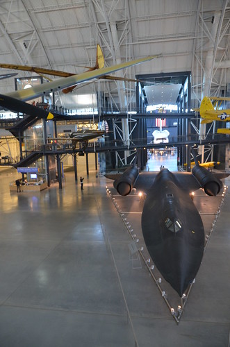
Steven F. Udvar-Hazy Center: Lockheed SR-71 Blackbird port panorama (Bowlus 1-S-2100 Senior Albatross “Falcon” overhead)
rapid prototype china
Image by Chris Devers
See much more images of this, and the Wikipedia post.

Details, quoting from Smithsonian National Air and Space Museum | Bowlus 1-S-2100 Senior Albatross &quotFalcon&quot

Hawley Bowlus created the Senior Albatross series from a style he named the Bowlus Super Sailplane. In Germany, designers and pilots led the globe in the building and flying of high-overall performance gliders, and Bowlus was strongly influenced by their work. He and German glider pioneer, Martin Schempp, taught courses in aircraft style and construction at the Curtiss-Wright Technical Institute in Glendale, California. The two instructors led a group of students that constructed the Super Sailplane in 1932. The Super’ served as a prototype for the Senior Albatross.

In May possibly 1934, Warren E. Eaton acquired the Senior Albatross now preserved at NASM from Hawley Bowlus. Eaton joined the U. S. Army Air Service and flew SPAD XIII fighters (see NASM collection) in the 103rd Aero Squadron, 3rd Pursuit Group, at Issoudon, France, from August 27, 1918, to the Armistice. He was credited with downing 1 enemy aircraft in aerial combat. Following the war, Eaton founded the Soaring Society of America and became that organization’s 1st president.

Gift of Mrs. Genevieve J. Eaton.

Manufacturer:
Bowlus-Dupont Sailplane Firm

Date:
1933

Nation of Origin:
United States of America

Dimensions:
Wingspan: 18.8 m (61 ft 9 in)
Length: 7.two m (23 ft 7 in)
Height: 1.six m (five ft 4 in)
Weight: Empty, 153 kg (340 lb) Gross, 236 kg (520 lb)

Supplies:
Initially skinned with mahogany and covered with lightweight cotton &quotglider cloth,&quot then covered with a shellac-primarily based varnish. In 2000, restorers removed original fabric and shellac coating, recovered with Grade A cotton fabric followed by a number of coats of nitrate dope, then lemon shellac, finishing with numerous coats of Johnson Wax.

Physical Description:
Monoplane glider with strut-braced, gull-type wing mounted high on monocoque fuselage wooden construction with steel and aluminum fittings and controls fuselage and wing leading edge covered with mahogany plywood. Fuselage skin applied more than laminated Spruce bulkheads. Landing gear consists of single-wheel and …. [size?] tire mounted beneath forward fuselage, spring-steel tail skid beneath rudder.

Cockpit covered with hood produced from laminated Spruce bulkheads and covered with Mahogany plywood. Circular openings reduce into hood on either side of pilot’s head. Instrumentation: altimeter, airspeed, variometer plus a bank-and-turn indicator powered by low-speed venturi tube installed on retractable mount beneath appropriate wingroot.

Locations aft of wing spar and all manage surfaces covered with glider cloth. Cloth is doped straight onto ribs and plywood skin with no stitching for smooth finish. Continual-chord wing from fuselage to mid-span, tapered profile from mid-span to wingtip continuous-chord,
split-trailing edge flaps and high-aspect ratio ailerons. A Gö 549 airfoil is employed at the wing root, becoming symmetrical at the tip.

All-flying elevator mounted on duraluminum torque-tube, rudder hinged to box-beam post, each surfaces built up from Spruce and covered with glider cloth.

Long Description:
Long prior to he developed and built the Bowlus-DuPont &quotFalcon,&quot William Hawley Bowlus had contributed to aviation history. In 1926, T. Claude Ryan hired him as factory manager at the Ryan Airlines, Inc., plant at San Diego, California. Late in February 1927, Bowlus and twenty Ryan workmen, supervised by chief engineer Donald A. Hall and Charles A. Lindbergh, built a lengthy-range monoplane primarily based on the Ryan M-two. Lindbergh christened the modified M-two the &quotSpirit of St. Louis.&quot It is said that Bowlus suggested many design functions that Lindbergh approved and incorporated in the finished airplane. Bowlus renewed his friendship with Lindbergh late in 1929. He taught the ocean flyer and his wife, Anne Morrow, to fly sailplanes and in January 1930, each Charles and Anne completed their 1st solo glider flights.

Hawley Bowlus developed the Senior Albatross series from a design that he called the Bowlus Super Sailplane. In Germany, designers and pilots led the planet in developing and flying higher-efficiency gliders and Bowlus was strongly influenced by their function. He and German glider pioneer, Martin Schempp, taught courses in aircraft style and building at the Curtiss-Wright Technical Institute in Glendale, California. The two instructors led a group of students who constructed the Super Sailplane in 1932. The Super Sailplane served as a prototype for the Senior Albatross. The wing of the Super was nearly a copy of the German &quotWein&quot sailplane designed and flown with fantastic achievement in 1930 and 1931 by Robert Kronfeld. Both gliders employed the identical Goettingen 549 wing airfoil and even the ideas of the manage surfaces curved to practically identical contours. When Bowlus built the Senior Albatross series, the cockpit enclosure closely resembled another record-setting and influential German sailplane, the &quotFafnir,&quot made by Alexander Lippisch especially for pilot Gunther Groenhoff.

Richard C. du Pont was also an essential character in the history of the Senior Albatross. By the time he completed higher school, this heir to the Delaware-based chemical empire could fly gliders with some ability. During his very first year at the University of Virginia, he founded a campus soaring club. His passion for motorless flight drew him farther away from traditional academics and in 1932, he transferred to the Curtiss-Wright Technical Institute. Du Pont was almost certainly among the students who constructed the Super Albatross.

In 1933, du Pont teamed with Hawley Bowlus and the two males set up shop in San Fernando, California, to create gliders. Bowlus furnished the style experience and performed much of the construction. Du Pont supplied enthusiasm, labor, and financing. The Bowlus-DuPont Sailplane Company became an official entity in 1934 not in California, but in Delaware. The firm folded in September 1936 but for the duration of its quick corporate life, the tiny factory built 4 examples of the Senior Albatross but no two have been constructed specifically alike. All 4 sailplanes did have ‘gull’ wings (every wing was bent down slightly at about mid-span) and this function differentiates these airplanes from the prototype Super Sailplane. Bowlus fitted two with wing flaps, rather than spoilers, for better speed and altitude manage throughout landing. Mahogany plywood skinned one particular and spruce plywood covered the other 3 aircraft. Bowlus sold each of these handcrafted airplanes for ,500.

In 1935, Hawley Bowlus started work on a two-seat Senior Albatross constructed from aluminum but other distractions delayed completion till 1940. In 1939, Ernest Langley and Jim Gough built one more Senior Albatross at the Bowlus ranch in California.

Functionality calculations revealed a ideal glide ratio of 23:1 when flying at 64.four kph (40 mph). If it became required, the pilot of a Senior Albatross could push his mount well more than 161 kph (100 mph) as long as he never ever exceeded a speed of 241.five kph (150 mph). With an accomplished pilot at the controls, the Senior Albatross could fly greater than any American airplane without a motor and they had been very pleasing to look at also. A quotation from the July 1934 problem of &quotAviation,&quot a popular periodical, sums up a single writer’s impressions of the Bowlus-Du Pont Senior Albatross:

&quotFew flying machines have ever exhibited such an extraordinary combination of workmanship, finish, and aerodynamic refinement, so that it seems really protected to say that the new ships represent the ultimate in soaring style practice in the United States, if not the globe.&quot

The pilots who flew the Senior Albatross practically dominated American competitive soaring. In 1933, Richard du Pont flew the first Senior Albatross at the fourth U. S. National Soaring Championships held at Elmira, New York. On September 21, du Pont set the American sailplane distance record by flying 196 km (121.6 miles). On June 25, 1934, he flew to inside three.two km (two miles) of New York City and established a new globe distance record of 254 km (158 miles). On June 30, 1934, du Pont set the U. S. altitude record for sailplanes by climbing to 1,892 m (six,223 ft). The following year, Lewin Barringer soared his Senior Albatross parallel to the ridges of the Allegheny Mountains for 250.three km (155.five miles).

In May possibly 1934, Warren E. Eaton acquired from Hawley Bowlus the Senior Albatross that is now preserved at NASM. Eaton was currently a veteran aviator. He had joined the U. S. Army Air Service and flew SPAD XIII fighters (see NASM collection) in the 103rd Aero Squadron, 3rd Pursuit Group, at Issoudon, France, from August 27, 1918, until Armistice Day, November 11. He was credited with downing one particular enemy aircraft in aerial combat. Soon after the war, Eaton founded the Soaring Society of America and became that organization’s initial president.

Eaton had commissioned Bowlus to build this glider after he saw Richard C. du Pont fly the second Senior Albatross at the U. S. Nationals the year ahead of. Eaton’s ordered flaps for his aircraft and it was the only Senior Albatross skinned with mahogany plywood. He christened it &quotFalcon&quot and it bore the federal aircraft registration number G13763. Many gold decals edged in black also appeared at a variety of locations on the fuselage. &quotWarren E. Eaton&quot and &quotFalcon&quot appeared on both sides of the nose. A stylized albatross and the firm motto &quotOn the Wings of an Albatross&quot were applied to the vertical fin above the words &quotBowlus-Du Pont Sailplane Company.&quot

Eaton initial flew the glider at San Diego. In June, he brought it to the national contest at Harris Hill, New York. At Huge Meadows, Virginia, Eaton set the American soaring altitude record, two,765 m (9,094 ft), during September 1934. 3 months later, Eaton died in Florida flying a Franklin p glider.

In 1935, Warren Eaton’s widow, Genevieve, donated the &quotFalcon&quot to the Smithsonian Institution. It arrived in Washington on May possibly 28 and a handful of days later, museum personnel suspended the glider from the ceiling of the West Hall of the Arts and Industries Developing where it remained on display for several years.

• • • • •

See much more photographs of this, and the Wikipedia article.

Specifics, quoting from Smithsonian National Air and Space Museum | Lockheed SR-71 Blackbird:

No reconnaissance aircraft in history has operated globally in a lot more hostile airspace or with such total impunity than the SR-71, the world’s fastest jet-propelled aircraft. The Blackbird’s performance and operational achievements placed it at the pinnacle of aviation technologies developments throughout the Cold War.

This Blackbird accrued about 2,800 hours of flight time during 24 years of active service with the U.S. Air Force. On its final flight, March 6, 1990, Lt. Col. Ed Yielding and Lt. Col. Joseph Vida set a speed record by flying from Los Angeles to Washington, D.C., in 1 hour, four minutes, and 20 seconds, averaging three,418 kilometers (2,124 miles) per hour. At the flight’s conclusion, they landed at Washington-Dulles International Airport and turned the airplane over to the Smithsonian.

Transferred from the United States Air Force.

Manufacturer:
Lockheed Aircraft Corporation

Designer:
Clarence L. &quotKelly&quot Johnson

Date:
1964

Country of Origin:
United States of America

Dimensions:
All round: 18ft five 15/16in. x 55ft 7in. x 107ft 5in., 169998.5lb. (five.638m x 16.942m x 32.741m, 77110.8kg)
Other: 18ft 5 15/16in. x 107ft 5in. x 55ft 7in. (five.638m x 32.741m x 16.942m)

Components:
Titanium

Physical Description:
Twin-engine, two-seat, supersonic strategic reconnaissance aircraft airframe constructed largley of titanium and its alloys vertical tail fins are constructed of a composite (laminated plastic-variety material) to decrease radar cross-section Pratt and Whitney J58 (JT11D-20B) turbojet engines feature large inlet shock cones.

Cool Rapid Prototype China photos

Check out these fast prototype china photos:

Steven F. Udvar-Hazy Center: main hall panorama (SR-71, Space Shuttle, et al)
rapid prototype china
Image by Chris Devers
See far more photos of this, and the Wikipedia write-up.

Specifics, quoting from Smithsonian National Air and Space Museum | Lockheed SR-71 Blackbird:

No reconnaissance aircraft in history has operated globally in much more hostile airspace or with such total impunity than the SR-71, the world’s fastest jet-propelled aircraft. The Blackbird’s functionality and operational achievements placed it at the pinnacle of aviation technology developments throughout the Cold War.

This Blackbird accrued about two,800 hours of flight time during 24 years of active service with the U.S. Air Force. On its last flight, March six, 1990, Lt. Col. Ed Yielding and Lt. Col. Joseph Vida set a speed record by flying from Los Angeles to Washington, D.C., in 1 hour, four minutes, and 20 seconds, averaging three,418 kilometers (two,124 miles) per hour. At the flight’s conclusion, they landed at Washington-Dulles International Airport and turned the airplane more than to the Smithsonian.

Transferred from the United States Air Force.

Manufacturer:
Lockheed Aircraft Corporation

Designer:
Clarence L. &quotKelly&quot Johnson

Date:
1964

Nation of Origin:
United States of America

Dimensions:
General: 18ft 5 15/16in. x 55ft 7in. x 107ft 5in., 169998.5lb. (5.638m x 16.942m x 32.741m, 77110.8kg)
Other: 18ft 5 15/16in. x 107ft 5in. x 55ft 7in. (five.638m x 32.741m x 16.942m)

Components:
Titanium

Physical Description:
Twin-engine, two-seat, supersonic strategic reconnaissance aircraft airframe constructed largley of titanium and its alloys vertical tail fins are constructed of a composite (laminated plastic-sort material) to minimize radar cross-section Pratt and Whitney J58 (JT11D-20B) turbojet engines function massive inlet shock cones.

• • • • •

See far more pictures of this, and the Wikipedia write-up.

Particulars, quoting from Smithsonian National Air and Space Museum | Space Shuttle Enterprise:

Manufacturer:
Rockwell International Corporation

Country of Origin:
United States of America

Dimensions:
Overall: 57 ft. tall x 122 ft. extended x 78 ft. wing span, 150,000 lb.
(1737.36 x 3718.57 x 2377.44cm, 68039.6kg)

Components:
Aluminum airframe and physique with some fiberglass features payload bay doors are graphite epoxy composite thermal tiles are simulated (polyurethane foam) except for test samples of actual tiles and thermal blankets.

The initial Space Shuttle orbiter, &quotEnterprise,&quot is a full-scale test vehicle utilized for flights in the atmosphere and tests on the ground it is not equipped for spaceflight. Though the airframe and flight handle elements are like those of the Shuttles flown in space, this automobile has no propulsion system and only simulated thermal tiles because these attributes have been not necessary for atmospheric and ground tests. &quotEnterprise&quot was rolled out at Rockwell International’s assembly facility in Palmdale, California, in 1976. In 1977, it entered service for a nine-month-long approach-and-landing test flight plan. Thereafter it was employed for vibration tests and match checks at NASA centers, and it also appeared in the 1983 Paris Air Show and the 1984 World’s Fair in New Orleans. In 1985, NASA transferred &quotEnterprise&quot to the Smithsonian Institution’s National Air and Space Museum.

Transferred from National Aeronautics and Space Administration

Cool Fast Prototyping pictures

Check out these rapidly prototyping pictures:

portal turret
fast prototyping
Image by eok.gnah
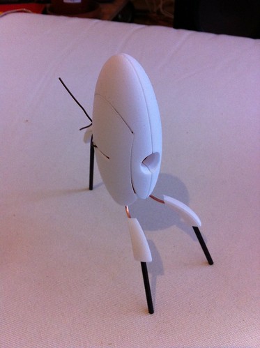
fast test how the components come with each other
(operate in progress)

Individual Improvement Workshop Prototyping
fast prototyping
Image by eekim
Day 153 of 2015. A single of the surprising uses that has emerged for the DIY Method / Culture kit that Amy Wu and I have been building for more than a year now has been for personal improvement. Amy and I are playing with a quantity of workshop possibilities, and we prototyped a private improvement workshop with my buddy, Sarah, nowadays.

Cool Cnc Engineering Solutions pictures

A handful of good cnc engineering services images I found:

Blackened steel stair with stainless treads
cnc engineering services
Image by Caliper Studio
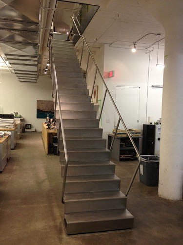
Center stringer comfort stair connects two office floors in Starret Lehigh constructing. Stringer and slab edge assemblies are blackened. Twenty four stainless steel treads are welded to the stringer form a continuous ribbon. 1 1/4&quot diameter handrail posts are continuous bent &quotC&quot shapes that wrap about treds and are welded to stringer. Stair will be delivered to site in a single piece [24′ lengthy 3′ wide 3′ tall @ 2000lbs].

Design and style by Diller Scofidio + Renfro

Detailing, Fabrication and Installation by Caliper Studio. Caliper Studio engaged Eckersley O’Callaghan &amp partners for engineering services.