Cool Machining Engineering images

Cool Machining Engineering images

Some cool machining engineering pictures:

Image from web page 485 of “American engineer and railroad journal” (1893)
machining engineering
Image by World wide web Archive Book Photos
Identifier: americanengineer68newy
Title: American engineer and railroad journal
Year: 1893 (1890s)
Authors:
Subjects: Railroad engineering Engineering Railroads Railroad cars
Publisher: New York : M.N. Forney
Contributing Library: Carnegie Library of Pittsburgh
Digitizing Sponsor: Lyrasis Members and Sloan Foundation

View Book Web page: Book Viewer
About This Book: Catalog Entry
View All Photos: All Pictures From Book

Click right here to view book on-line to see this illustration in context in a browseable on the internet version of this book.

Text Appearing Before Image:
qually satisfactory. The tiny enginedrives drills and valve-facing tools straight by implies of theStow flexible shaft. The identical practise also prevails here, ason the other road, in the building of pistons. A hollowpislon with rings sprung in is employed, but the rings are muchnarrower than on the New York, Lake Erie &amp Western. Mr.Foster makes use of a ring only | in. wide, and finds them perfectlysatisfactory. There is a strategy of holding the split rings out 496 THE AMERICAN ENGINEER [November, 1894. right here, nonetheless, that—to us at least—is novel. It is well knownthat if a ring is turned to a bigger diameter than that of thecylinder in which it is to run, when it is sprung in it will beout of round. To obviate this difficulty and, at the same time,hold an outward pressure on the ring, it is turned to match thecylinder. Yet another and slightly heavier ring is turned to adiameter a trifle bigger than the inside of the outer ring, andthe outer ring slipped more than it. Then, wheu they are both com-

Text Appearing Soon after Image:
BALANCED VALVE, FALL BROOK COAL CO. pressed and place in thecylinder, the outer ring is round, whilethe inner keeps it nicely out against the walls. The vehicle shops adjoin the machine shop, and are fitted withthe usual complement of woodworking tools. The floor roomconsists of three tracks, each capable of holding 5 automobiles. AllCars coming in for rebuilding and all new rolling stock areequipped with the Gould coupler and the Westinghouse airbrake. The nicknames bestowed up-on a variety of varieties of locomotivesby the men constructing or runningthem have come to have a trulytechnical significance but it is sel-dom that a nickname is acceptedby the motive energy departmentwith the gravity of a name appliedto one particular of the locomotives on thisroad. All the engines have namesas nicely as numbers, although theformer are a mere ornament andnot used in reports or orders. Acertain locomotive had the misfor-tune to jump from a high trestle atIthaca, and was forthwith dubbedthe Sam Patrh by the males. Re-pairs naturally

Note About Pictures
Please note that these pictures are extracted from scanned page images that might have been digitally enhanced for readability – coloration and appearance of these illustrations may possibly not completely resemble the original work.

Image from page 423 of “Manual for railroad engineers and engineering students : containing the guidelines and tables necessary for the location, building, and equipment of railroads as constructed in the United States” (1883)
machining engineering
Image by Web Archive Book Pictures
Identifier: manualforrailroa00vose
Title: Manual for railroad engineers and engineering students : containing the rules and tables needed for the place, building, and equipment of railroads as constructed in the United States
Year: 1883 (1880s)
Authors: Vose, George L. (George Leonard), 1831-1910
Subjects: Railroad engineering
Publisher: Boston : Lee and Shepard
Contributing Library: Northeastern University, Snell Library
Digitizing Sponsor: Northeastern University, Snell Library

View Book Page: Book Viewer
About This Book: Catalog Entry
View All Images: All Pictures From Book

Click right here to view book on-line to see this illustration in context in a browseable on-line version of this book.

Text Appearing Before Image:
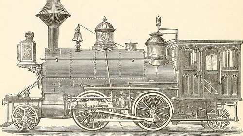
Fig- 157- Fig. 157 and the addition of a related truck behind gives thetank engine, made by Mr. Hudson, of the Rogers Locomotive 398 MANUAL FOR RAILROAD ENGINEERS. Functions, shown in Fig. 158, a most excellent machine for switching,construction, branch, and even light passenger service.*

Text Appearing Soon after Image:
Fig. 158. Iig- 1S9 shows a six-wheeled tank engine, which, upon a toler-ably straight track, is a quite effective machine, but upon sharp

Note About Images
Please note that these images are extracted from scanned web page photos that may possibly have been digitally enhanced for readability – coloration and look of these illustrations may not completely resemble the original work.

Cool Metal Components China pictures

Cool Metal Components China pictures

Verify out these metal components china images:

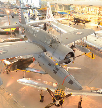
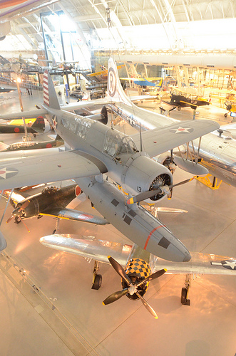
Steven F. Udvar-Hazy Center: South hangar panorama, like Vought OS2U-three Kingfisher seaplane & B-29 Enola Gay, among other folks
metal parts china
Image by Chris Devers
Quoting Smithsonian National Air and Space Museum | Vought OS2U-3 Kingfisher:

The Kingfisher was the U.S. Navy’s primary ship-based, scout and observation aircraft throughout Globe War II. Revolutionary spot welding methods gave it a smooth, non-buckling fuselage structure. Deflector plate flaps that hung from the wing’s trailing edge and spoiler-augmented ailerons functioned like extra flaps to let slower landing speeds. Most OS2Us operated in the Pacific, where they rescued several downed airmen, including Globe War I ace Eddie Rickenbacker and the crew of his B-17 Flying Fortress.

In March 1942, this airplane was assigned to the battleship USS Indiana. It later underwent a six-month overhaul in California, returned to Pearl Harbor, and rejoined the Indiana in March 1944. Lt. j.g. Rollin M. Batten Jr. was awarded the Navy Cross for generating a daring rescue in this airplane below heavy enemy fire on July four, 1944.

Transferred from the United States Navy.

Manufacturer:
Vought-Sikorsky Aircraft Division

Date:
1937

Country of Origin:
United States of America

Dimensions:
General: 15ft 1 1/8in. x 33ft 9 1/2in., 4122.6lb., 36ft 1 1/16in. (460 x 1030cm, 1870kg, 1100cm)

Materials:
Wings covered with fabric aft of the main spar

Physical Description:
Two-seat monoplane, deflector plate flaps hung from the trailing edge of the wing, ailerons drooped at low airspeeds to function like added flaps, spoilers.

• • • • •

Quoting Smithsonian National Air and Space Museum | Boeing B-29 Superfortress &quotEnola Gay&quot:

Boeing’s B-29 Superfortress was the most sophisticated propeller-driven bomber of World War II and the 1st bomber to property its crew in pressurized compartments. Despite the fact that created to fight in the European theater, the B-29 located its niche on the other side of the globe. In the Pacific, B-29s delivered a selection of aerial weapons: standard bombs, incendiary bombs, mines, and two nuclear weapons.

On August 6, 1945, this Martin-built B-29-45-MO dropped the first atomic weapon used in combat on Hiroshima, Japan. 3 days later, Bockscar (on display at the U.S. Air Force Museum near Dayton, Ohio) dropped a second atomic bomb on Nagasaki, Japan. Enola Gay flew as the advance weather reconnaissance aircraft that day. A third B-29, The Fantastic Artiste, flew as an observation aircraft on both missions.

Transferred from the United States Air Force.

Manufacturer:
Boeing Aircraft Co.
Martin Co., Omaha, Nebr.

Date:
1945

Nation of Origin:
United States of America

Dimensions:
General: 900 x 3020cm, 32580kg, 4300cm (29ft 6 5/16in. x 99ft 1in., 71825.9lb., 141ft 15/16in.)

Components:
Polished overall aluminum finish

Physical Description:
4-engine heavy bomber with semi-monoqoque fuselage and higher-aspect ratio wings. Polished aluminum finish all round, standard late-Globe War II Army Air Forces insignia on wings and aft fuselage and serial quantity on vertical fin 509th Composite Group markings painted in black &quotEnola Gay&quot in black, block letters on reduce left nose.

Thames Festival Finale Fireworks
metal parts china
Image by Dominic’s pics
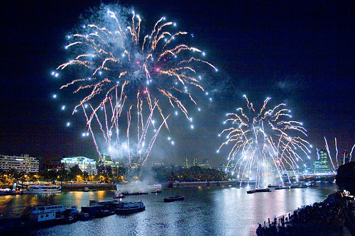
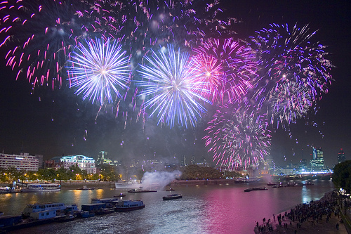
Element of a Set / Virtual Firework Display Slideshow documenting the firework show that marked the finish of the &quotthe mayor’s&quot Thames Festival in London on the evening of Sunday September 11th 2011.

The display was presented by Pains Fireworks.

A delay in the start of the display from the scheduled time was attributed by the crowds to incompetence by &quotBumbling Boris&quot Johnson – the London Mayor – component of the British patrician &quotlimited liability&quot ruling class. &quotI’m in charge, but if something goes wrong, somebody else will be sacked…&quot

Like the extreme audio dynamic variety of Taiko or Samba drumming, it is not truly feasible to record the visual brilliance of fireworks with a camera. You have to experience firework displays live, in individual. These photos had been taken at the slowest sensor speed (ISO one hundred), maximum aperture (to minimise diffraction &quotglare&quot effects) and with a variety of exposure times ranging from about .5 to 2 seconds. The intense light brought on some &quotbleaching&quot of the paths of the lights, and so the colours have been enriched if Photoshop. (In retrospect I might have used a slightly smaller aperture.)In addition, the river and land regions have been selectively lightened in Photoshop. Fortuitously, a gentle breeze caused the smoke to drift eastwards, away from my vantage point on Waterloo Bridge, so the view of the fireworks was fairly unobstructed by smoke.

Fireworks date from at least the 7th century in China. The colours are believed to have been conventional incandescent &quotblack physique&quot bonfire colours: red, orange, yellow and white. (It is theoretically possible to make pale blue just by heating, but this needs impracticably high temperatures. It is not feasible to heat anything to &quotgreen hot&quot or &quotpurple hot&quot.) It is believed that from about 1830 in Italy metal salts were introduced to create a wider, richer hued, spectrum of colours by chemical luminescence. This strategy can be problematic, as it can be tough to produce stable, sensible, chemical compositions. It has been suggested that some shades of green are nevertheless tough to achieve.

See also:

Fireworks [Wikipedia]
Firework Colours [The chemistry of Fireworks by Reema Gondhia, Imperial College]
History of fireworks [Pyro Universe]

Thames Festival Finale Fireworks
metal parts china
Image by Dominic’s pics
Component of a Set / Virtual Firework Show Slideshow documenting the firework show that marked the finish of the &quotthe mayor’s&quot Thames Festival in London on the evening of Sunday September 11th 2011.

The show was presented by Pains Fireworks.

A delay in the start off of the show from the scheduled time was attributed by the crowds to incompetence by &quotBumbling Boris&quot Johnson – the London Mayor – element of the British patrician &quotlimited liability&quot ruling class. &quotI’m in charge, but if something goes incorrect, somebody else will be sacked…&quot

Like the intense audio dynamic variety of Taiko or Samba drumming, it is not actually feasible to record the visual brilliance of fireworks with a camera. You have to knowledge firework displays live, in individual. These photos have been taken at the slowest sensor speed (ISO one hundred), maximum aperture (to minimise diffraction &quotglare&quot effects) and with a assortment of exposure occasions ranging from about .5 to 2 seconds. The intense light caused some &quotbleaching&quot of the paths of the lights, and so the colours have been enriched if Photoshop. (In retrospect I may have used a slightly smaller aperture.)Additionally, the river and land locations have been selectively lightened in Photoshop. Fortuitously, a gentle breeze triggered the smoke to drift eastwards, away from my vantage point on Waterloo Bridge, so the view of the fireworks was fairly unobstructed by smoke.

Fireworks date from at least the 7th century in China. The colours are believed to have been standard incandescent &quotblack physique&quot bonfire colours: red, orange, yellow and white. (It is theoretically possible to generate pale blue just by heating, but this demands impracticably high temperatures. It is not achievable to heat some thing to &quotgreen hot&quot or &quotpurple hot&quot.) It is believed that from about 1830 in Italy metal salts were introduced to make a wider, richer hued, spectrum of colours by chemical luminescence. This strategy can be problematic, as it can be challenging to produce stable, practical, chemical compositions. It has been suggested that some shades of green are nonetheless difficult to achieve.

See also:

Fireworks [Wikipedia]
Firework Colours [The chemistry of Fireworks by Reema Gondhia, Imperial College]
History of fireworks [Pyro Universe]

Cool China Prototyping photos

Cool China Prototyping photos

A handful of good china prototyping pictures I identified:

pfc_07_08-copy-1
china prototyping
Image by core.formula
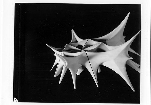
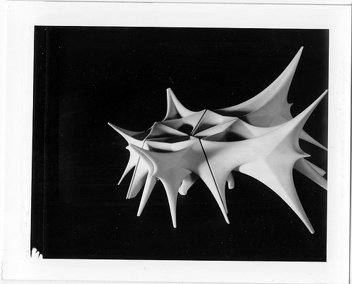
A collection of fast prototyping models (ZPrint) produced in the Pratt Institute School of Architecture 2007 PreFab China Style Studio:Evan Douglis, Richard Sarrach, Che-Wei Wang, Eric Wong

Operate made by: Dan Breitner, Andres Correa , Brad Rothenberg

Please go to www.core.kind-ula.com + www.prefabchina.com for much more

Cool Metal Parts China pictures

Some cool metal components china pictures:

Steven F. Udvar-Hazy Center: View down onto SR-71 Blackbird & Boeing P-26A Peashooter
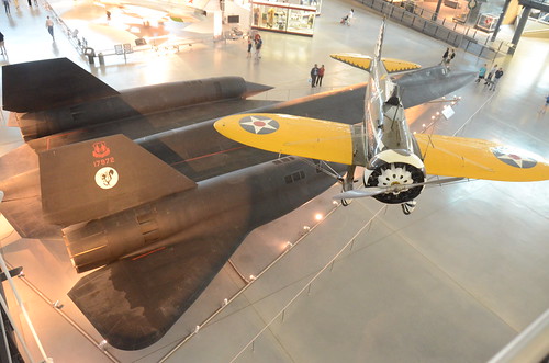
metal parts china
Image by Chris Devers
See much more images of this, and the Wikipedia post.

Specifics, quoting from Smithsonian National Air and Space Museum | Boeing P-26A Peashooter:

The Boeing P-26A of the mid-to-late 1930s introduced the idea of the higher-functionality, all-metal monoplane fighter design and style, which would grow to be common during World War II. A radical departure from wood-and-fabric biplanes, the Peashooter nonetheless retained an open cockpit, fixed landing gear, and external wing bracing.

Most P-26As stationed overseas were at some point sold to the Philippines or assigned to the Panama Canal Department Air Force, a branch of the U.S. Army Air Corps. Several went to China and a single to Spain. This a single was based at Selfridge Field in Michigan and Fairfield Air Depot in Ohio amongst its acceptance by the U.S. Army Air Corps in 1934 and its transfer to the Canal Zone in 1938. It was offered to Guatemala in 1942 and flew in the Guatemalan air force till 1954. Guatemala donated it to the Smithsonian in 1957.

Gift of the Guatemalan Air Force, Republic of Guatemala

Manufacturer:
Boeing Aircraft Co.

Date:
1934

Nation of Origin:
United States of America

Dimensions:
Wingspan: 8.5 m (27 ft 11 in)
Length:7.three m (23 ft 11 in)
Height:3.1 m (ten ft two in)
Weight, empty:996 kg (two,196 lb)
Weight, gross:1,334 kg (2,935 lb)
Best speed:377 km/h (234 mph)
Engine:Pratt &amp Whitney R-1340-27, 600 hp
Armament:two .30 cal. M2 Browning aircraft machine guns

• • •

Quoting from Boeing History | P-26 &quotPeashooter&quot Fighter:

The all-metal, single-wing P-26, popularly identified as the &quotPeashooter,&quot was an totally new design and style for Boeing, and its structure drew heavily on the Monomail. The Peashooter’s wings were braced with wire, rather than with the rigid struts employed on other airplanes, so the airplane was lighter and had significantly less drag. Its initial high landing speeds had been lowered by the addition of wing flaps in the production models.

Due to the fact the P-26 flew 27 mph faster and outclimbed biplane fighters, the Army ordered 136 production-model Peashooters. Acclaimed by pilots for its speed and maneuverability, the small but feisty P-26 formed the core of pursuit squadrons all through the United States.

Twelve export versions, 11 for China and 1 for Spain, had been built. 1 of a group of P-26s, turned more than to the Philippine Army late in 1941, was among the very first Allied fighters to down a Japanese airplane in Globe War II.

Funds to purchase the export version of the Peashooter were partly raised by Chinese Americans. Contribution boxes have been placed on the counters of Chinese restaurants.

Specifications

• Very first flight: March 20, 1932
• Model number: 248/266
• Classification: Fighter
• Span: 28 feet
• Length: 23 feet 7 inches
• Gross weight: two,995 pounds
• Best speed: 234 mph
• Cruising speed: 200 mph
• Range: 635 miles
• Ceiling: 27,400 feet
• Power: 600-horsepower P&ampW Wasp engine
• Accommodation: 1 pilot
• Armament: 2 machine guns, 200-pound bomb load

• • • • •

See a lot more pictures of this, and the Wikipedia report.

Particulars, quoting from Smithsonian National Air and Space Museum | Lockheed SR-71 Blackbird:

No reconnaissance aircraft in history has operated globally in more hostile airspace or with such full impunity than the SR-71, the world’s fastest jet-propelled aircraft. The Blackbird’s performance and operational achievements placed it at the pinnacle of aviation technologies developments for the duration of the Cold War.

This Blackbird accrued about 2,800 hours of flight time during 24 years of active service with the U.S. Air Force. On its final flight, March six, 1990, Lt. Col. Ed Yielding and Lt. Col. Joseph Vida set a speed record by flying from Los Angeles to Washington, D.C., in 1 hour, four minutes, and 20 seconds, averaging 3,418 kilometers (2,124 miles) per hour. At the flight’s conclusion, they landed at Washington-Dulles International Airport and turned the airplane over to the Smithsonian.

Transferred from the United States Air Force.

Manufacturer:
Lockheed Aircraft Corporation

Designer:
Clarence L. &quotKelly&quot Johnson

Date:
1964

Country of Origin:
United States of America

Dimensions:
All round: 18ft 5 15/16in. x 55ft 7in. x 107ft 5in., 169998.5lb. (5.638m x 16.942m x 32.741m, 77110.8kg)
Other: 18ft five 15/16in. x 107ft 5in. x 55ft 7in. (5.638m x 32.741m x 16.942m)

Materials:
Titanium

Physical Description:
Twin-engine, two-seat, supersonic strategic reconnaissance aircraft airframe constructed largley of titanium and its alloys vertical tail fins are constructed of a composite (laminated plastic-type material) to minimize radar cross-section Pratt and Whitney J58 (JT11D-20B) turbojet engines function large inlet shock cones.

Extended Description:
No reconnaissance aircraft in history has operated in more hostile airspace or with such full impunity than the SR-71 Blackbird. It is the fastest aircraft propelled by air-breathing engines. The Blackbird’s overall performance and operational achievements placed it at the pinnacle of aviation technology developments in the course of the Cold War. The airplane was conceived when tensions with communist Eastern Europe reached levels approaching a complete-blown crisis in the mid-1950s. U.S. military commanders desperately required precise assessments of Soviet worldwide military deployments, especially near the Iron Curtain. Lockheed Aircraft Corporation’s subsonic U-two (see NASM collection) reconnaissance aircraft was an able platform but the U. S. Air Force recognized that this relatively slow aircraft was already vulnerable to Soviet interceptors. They also understood that the fast development of surface-to-air missile systems could place U-2 pilots at grave threat. The danger proved reality when a U-two was shot down by a surface to air missile over the Soviet Union in 1960.

Lockheed’s 1st proposal for a new high speed, higher altitude, reconnaissance aircraft, to be capable of avoiding interceptors and missiles, centered on a design propelled by liquid hydrogen. This proved to be impracticable since of considerable fuel consumption. Lockheed then reconfigured the design for traditional fuels. This was feasible and the Central Intelligence Agency (CIA), already flying the Lockheed U-2, issued a production contract for an aircraft designated the A-12. Lockheed’s clandestine ‘Skunk Works’ division (headed by the gifted design and style engineer Clarence L. &quotKelly&quot Johnson) developed the A-12 to cruise at Mach 3.two and fly properly above 18,288 m (60,000 feet). To meet these difficult requirements, Lockheed engineers overcame numerous daunting technical challenges. Flying much more than three instances the speed of sound generates 316° C (600° F) temperatures on external aircraft surfaces, which are sufficient to melt traditional aluminum airframes. The design team chose to make the jet’s external skin of titanium alloy to which shielded the internal aluminum airframe. Two standard, but extremely effective, afterburning turbine engines propelled this exceptional aircraft. These energy plants had to operate across a massive speed envelope in flight, from a takeoff speed of 334 kph (207 mph) to far more than three,540 kph (two,200 mph). To prevent supersonic shock waves from moving inside the engine intake causing flameouts, Johnson’s group had to style a complicated air intake and bypass method for the engines.

Skunk Operates engineers also optimized the A-12 cross-section style to exhibit a low radar profile. Lockheed hoped to obtain this by cautiously shaping the airframe to reflect as little transmitted radar energy (radio waves) as achievable, and by application of unique paint made to absorb, rather than reflect, these waves. This treatment became one of the first applications of stealth technologies, but it in no way totally met the style ambitions.

Test pilot Lou Schalk flew the single-seat A-12 on April 24, 1962, right after he became airborne accidentally in the course of higher-speed taxi trials. The airplane showed wonderful guarantee but it needed considerable technical refinement ahead of the CIA could fly the very first operational sortie on May possibly 31, 1967 – a surveillance flight more than North Vietnam. A-12s, flown by CIA pilots, operated as part of the Air Force’s 1129th Particular Activities Squadron under the &quotOxcart&quot system. While Lockheed continued to refine the A-12, the U. S. Air Force ordered an interceptor version of the aircraft designated the YF-12A. The Skunk Functions, nevertheless, proposed a &quotspecific mission&quot version configured to conduct post-nuclear strike reconnaissance. This program evolved into the USAF’s familiar SR-71.

Lockheed constructed fifteen A-12s, which includes a unique two-seat trainer version. Two A-12s have been modified to carry a specific reconnaissance drone, designated D-21. The modified A-12s have been redesignated M-21s. These had been created to take off with the D-21 drone, powered by a Marquart ramjet engine mounted on a pylon between the rudders. The M-21 then hauled the drone aloft and launched it at speeds higher adequate to ignite the drone’s ramjet motor. Lockheed also constructed 3 YF-12As but this variety in no way went into production. Two of the YF-12As crashed throughout testing. Only one particular survives and is on display at the USAF Museum in Dayton, Ohio. The aft section of a single of the &quotwritten off&quot YF-12As which was later employed along with an SR-71A static test airframe to manufacture the sole SR-71C trainer. One SR-71 was lent to NASA and designated YF-12C. Including the SR-71C and two SR-71B pilot trainers, Lockheed constructed thirty-two Blackbirds. The very first SR-71 flew on December 22, 1964. Since of intense operational expenses, military strategists decided that the far more capable USAF SR-71s should replace the CIA’s A-12s. These have been retired in 1968 after only one year of operational missions, mainly over southeast Asia. The Air Force’s 1st Strategic Reconnaissance Squadron (element of the 9th Strategic Reconnaissance Wing) took over the missions, flying the SR-71 starting in the spring of 1968.

After the Air Force began to operate the SR-71, it acquired the official name Blackbird– for the unique black paint that covered the airplane. This paint was formulated to absorb radar signals, to radiate some of the tremendous airframe heat generated by air friction, and to camouflage the aircraft against the dark sky at high altitudes.

Expertise gained from the A-12 system convinced the Air Force that flying the SR-71 safely essential two crew members, a pilot and a Reconnaissance Systems Officer (RSO). The RSO operated with the wide array of monitoring and defensive systems installed on the airplane. This gear included a sophisticated Electronic Counter Measures (ECM) technique that could jam most acquisition and targeting radar. In addition to an array of advanced, high-resolution cameras, the aircraft could also carry equipment made to record the strength, frequency, and wavelength of signals emitted by communications and sensor devices such as radar. The SR-71 was created to fly deep into hostile territory, avoiding interception with its tremendous speed and high altitude. It could operate safely at a maximum speed of Mach three.3 at an altitude much more than sixteen miles, or 25,908 m (85,000 ft), above the earth. The crew had to wear stress suits related to these worn by astronauts. These suits had been required to safeguard the crew in the event of sudden cabin pressure loss whilst at operating altitudes.

To climb and cruise at supersonic speeds, the Blackbird’s Pratt &amp Whitney J-58 engines have been made to operate continuously in afterburner. Although this would seem to dictate higher fuel flows, the Blackbird actually achieved its ideal &quotgas mileage,&quot in terms of air nautical miles per pound of fuel burned, throughout the Mach 3+ cruise. A common Blackbird reconnaissance flight may require several aerial refueling operations from an airborne tanker. Every time the SR-71 refueled, the crew had to descend to the tanker’s altitude, usually about six,000 m to 9,000 m (20,000 to 30,000 ft), and slow the airplane to subsonic speeds. As velocity decreased, so did frictional heat. This cooling effect caused the aircraft’s skin panels to shrink considerably, and these covering the fuel tanks contracted so a lot that fuel leaked, forming a distinctive vapor trail as the tanker topped off the Blackbird. As soon as the tanks had been filled, the jet’s crew disconnected from the tanker, relit the afterburners, and once more climbed to higher altitude.

Air Force pilots flew the SR-71 from Kadena AB, Japan, throughout its operational profession but other bases hosted Blackbird operations, too. The 9th SRW occasionally deployed from Beale AFB, California, to other places to carryout operational missions. Cuban missions had been flown directly from Beale. The SR-71 did not begin to operate in Europe till 1974, and then only temporarily. In 1982, when the U.S. Air Force primarily based two aircraft at Royal Air Force Base Mildenhall to fly monitoring mission in Eastern Europe.

When the SR-71 became operational, orbiting reconnaissance satellites had currently replaced manned aircraft to gather intelligence from websites deep inside Soviet territory. Satellites could not cover every geopolitical hotspot so the Blackbird remained a vital tool for global intelligence gathering. On several occasions, pilots and RSOs flying the SR-71 supplied details that proved essential in formulating productive U. S. foreign policy. Blackbird crews supplied critical intelligence about the 1973 Yom Kippur War, the Israeli invasion of Lebanon and its aftermath, and pre- and post-strike imagery of the 1986 raid carried out by American air forces on Libya. In 1987, Kadena-primarily based SR-71 crews flew a quantity of missions more than the Persian Gulf, revealing Iranian Silkworm missile batteries that threatened commercial shipping and American escort vessels.

As the performance of space-primarily based surveillance systems grew, along with the effectiveness of ground-based air defense networks, the Air Force began to shed enthusiasm for the costly system and the 9th SRW ceased SR-71 operations in January 1990. In spite of protests by military leaders, Congress revived the plan in 1995. Continued wrangling more than operating budgets, even so, quickly led to final termination. The National Aeronautics and Space Administration retained two SR-71As and the a single SR-71B for higher-speed research projects and flew these airplanes until 1999.

On March 6, 1990, the service profession of one Lockheed SR-71A Blackbird ended with a record-setting flight. This special airplane bore Air Force serial quantity 64-17972. Lt. Col. Ed Yeilding and his RSO, Lieutenant Colonel Joseph Vida, flew this aircraft from Los Angeles to Washington D.C. in 1 hour, four minutes, and 20 seconds, averaging a speed of three,418 kph (two,124 mph). At the conclusion of the flight, ‘972 landed at Dulles International Airport and taxied into the custody of the Smithsonian’s National Air and Space Museum. At that time, Lt. Col. Vida had logged 1,392.7 hours of flight time in Blackbirds, more than that of any other crewman.

This particular SR-71 was also flown by Tom Alison, a former National Air and Space Museum’s Chief of Collections Management. Flying with Detachment 1 at Kadena Air Force Base, Okinawa, Alison logged more than a dozen ‘972 operational sorties. The aircraft spent twenty-four years in active Air Force service and accrued a total of 2,801.1 hours of flight time.

Wingspan: 55’7&quot
Length: 107’5&quot
Height: 18’6&quot
Weight: 170,000 Lbs

Reference and Further Reading:

Crickmore, Paul F. Lockheed SR-71: The Secret Missions Exposed. Oxford: Osprey Publishing, 1996.

Francillon, Rene J. Lockheed Aircraft Given that 1913. Annapolis, Md.: Naval Institute Press, 1987.

Johnson, Clarence L. Kelly: A lot more Than My Share of It All. Washington D.C.: Smithsonian Institution Press, 1985.

Miller, Jay. Lockheed Martin’s Skunk Operates. Leicester, U.K.: Midland Counties Publishing Ltd., 1995.

Lockheed SR-71 Blackbird curatorial file, Aeronautics Division, National Air and Space Museum.

DAD, 11-11-01

Cool Precision Components Engineering pictures

Cool Precision Components Engineering pictures

A handful of nice precision components engineering pictures I located:

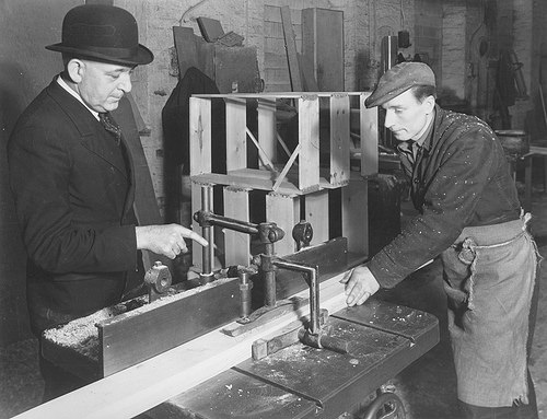
At perform in a shipyard joiners’ shop
precision parts engineering
Image by Tyne & Put on Archives & Museums
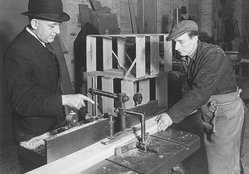
A scene from the Joiner’s shop of a Sunderland shipyard, probably that of Sir James Laing &amp Sons, January 1948, (TWAM ref. DS.JLT/5/four/two/5).

Sunderland has a remarkable history of innovation in shipbuilding and marine engineering. From the development of turret ships in the 1890s and the production of Doxford opposed piston engines following the Very first World War via to the designs for Liberty ships in the 1940s and SD14s in the 1960s. Sunderland has significantly to be proud of.

Tyne &amp Wear Archives cares for tens of thousands of photographs in its shipbuilding collections. Most of these concentrate on the ships – in distinct their construction, launch and sea trials. This set looks to redress the balance and to celebrate the operate of the guys and women who have played such a essential element in the region’s history. The images show the human side of this excellent story, with a lot of relating to the world famous shipbuilding and engineering firm William Doxford &amp Sons Ltd.

The Archives has created a brief weblog to accompany these photos.

(Copyright) We’re satisfied for you to share these digital photos inside the spirit of The Commons. Please cite ‘Tyne &amp Put on Archives &amp Museums’ when reusing. Specific restrictions on higher quality reproductions and industrial use of the original physical version apply although if you are unsure please email archives@twmuseums.org.uk

Not your usual SPARC
precision parts engineering
Image by nhr
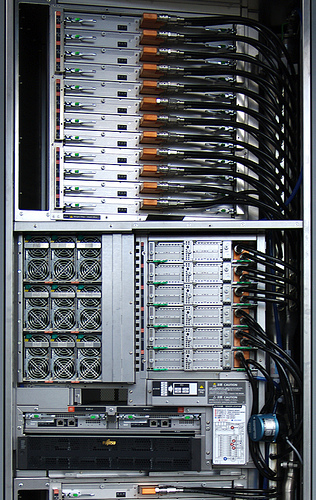
Spotted at a new datacenter: an interesting, custom SPARC-primarily based computing program for really huge scientific workloads — this rack is component of a computer cluster that can solve a system of linear equations with far more than ten million variables.

Each SPARC CPU is a 8-core chip clocked at 2GHz, and every single core has 256 (!) double precision floating-point registers and 4 multiply-add units. That quantity of FP registers is adequate to compute a 8×8 matrix multiplication with no requiring any access to RAM beyond the initial loading and final storing of the FP data. Accesses to the &quotslow&quot L1, L2 caches and RAM are as a result minimized, allowing the CPU to crunch numbers at higher speed.
Operations on massive matrixes can be effectively divided e.g. into 8×8 block decompositions that match in the register file.

Every multiply-add unit can output on each clock cycle the result of an operation of the kind D&nbsp:=&nbspA&nbsp*&nbspB&nbsp+&nbspC exactly where A, B and C are double precision FP numbers.

The SPARC CPU’s maximum FP throughput is thus 2GHz * eight cores * four fused mutiply-adds = 128 GFLOPs/CPU. Each SPARC CPU has a memory bandwidth of 64GBytes/s.

A SPARC CPU, together with 16GB of RAM and an Interconnect Controller (ICC), form a unified &quotcompute node&quot.
The ICC combines, on a single VLSI, 4 5GBytes/s DMA interfaces and a crossbar switch / router with ten 5GBytes/s bidirectional links. These ten links connect to other compute nodes, forming a virtual 6D fused torus / mesh network structure.
Compute nodes can access the memory of other nodes making use of virtual addressing, as a remote DMA operation. The ICC of the destination node performs the needed virtual to physical address translation and the actual DMA. The ICC can also perform easy arithmetic operations on integers and FP data, enabling the parallel computation by the communication fabric itself of barrier operations, without obtaining to involve the SPARC CPU.
Four compute nodes are integrated on each system board, and each rack holds 24 hot swappable program boards.

The image shows the upper twelve technique boards in a rack. Also visible are the nine air-cooled, redundant power supply units, the six I/O controller units, as effectively as two blade-like, redundant rack supervisor controllers and a Fujitsu storage array containing the operating technique boot disks.

The six I/O controller units are water-cooled, and every single includes a single unified compute node. These I/O controllers connect the rack to other racks and to a high-speed clustered local storage program with a capacity of about 11 petabytes, and a international file system of about 30 PBytes. The operating system of the unified compute nodes is a custom fault-resilient multi-core Linux kernel the mass storage technique is primarily based on Lustre.

The peak FP functionality of each rack is 128 GFLOPs/compute node * (4 compute nodes / method board * 24 technique boards + 6 I/O controller compute nodes ) / rack = 128GFLOPs * (four*24+6) = 13056 GFLOPs, or 13.056 TeraFLOPs the total memory size per rack is 1632 Gigabytes.

Every single rack requires about 10KW of electrical energy, and the higher-speed 6D torus inter-node connection fabric has been developed to efficiently extend to hundreds of such racks. Beware that electricity bill…

In this information center, a cluster of 864 of these racks kind a huge parallel supercomputer, with 1400 Terabytes of RAM, and a theoretical peak FP overall performance of 13.056 TFLOPs * 864 = 11.280 PetaFLOPs — i.e. more than eleven million gigaFLOPs.
The powerful LINPACK performance is about 93% of that theoretical peak.

The major intended application area seems to be the life sciences, with an emphasis on molecular modelling ab initio — simulating complete molecules starting from the quantum behavior of elementary nucleons and electrons — to assist the design of new drugs, simulate biochemical processes like chemotherapy agent resistance of cancer cells at the molecular level, model neural processes and so on.

Climate modelling, atomic level simulation of novel nanomaterials and computational fluid dynamics applications are also in the input queue.

Cool Cnc Engineering Services photos

Cool Cnc Engineering Services photos

A few nice cnc engineering solutions images I found:

Handrail Jog
cnc engineering services
Image by Caliper Studio
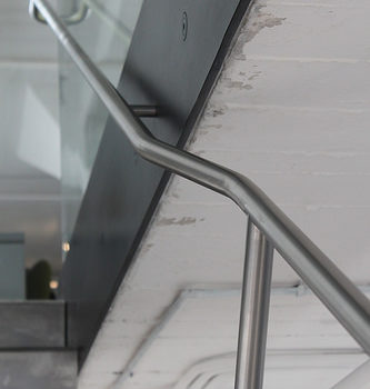
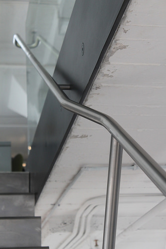
Center stringer comfort stair connects two office floors in Starret Lehigh developing. Stringer and slab edge assemblies are blackened. Twenty four stainless steel treads are welded to the stringer type a continuous ribbon. 1 1/4&quot diameter handrail posts are continuous bent &quotC&quot shapes that wrap about treds and are welded to stringer. Stair was delivered to internet site in one particular piece [24′ extended 3′ wide 3′ tall @ 2000lbs. Glass is two 1/2&quot layers of low iron tempered glass with PVB interlayer. Every panel is a 148.375&quotx41.25&quot rectangle that weighs 522lbs. Cut out in concrete floor is trimmed with a box of 1/2&quot thick blackened steel that was fully prewelded in the shop. The box picks up the load at best of stair and serves as a custom base shoe for the glass.

Style by Diller Scofidio + Renfro

Detailing, Fabrication and Installation by Caliper Studio. Caliper Studio engaged Eckersley O’Callaghan &amp partners for engineering solutions.

Cool Prototype Engineering pictures

Cool Prototype Engineering pictures

Check out these prototype engineering pictures:

Silver and Gold
prototype engineering
Image by NASA Goddard Photo and Video
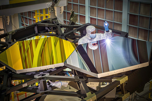
Inside NASA’s Goddard Space Flight Center’s giant clean area in Greenbelt, Md., JWST Optical Engineer Larkin Carey from Ball Aerospace, examines two test mirror segments recently placed on a black composite structure. This black composite structure is referred to as the James Webb Space Telescope’s “Pathfinder” and acts as a spine supporting the telescope’s principal mirror segments. The Pathfinder is a non-flight prototype.

The mirrors had been placed on Pathfinder employing a robotic arm move that involved hugely trained engineers and technicians from Exelis, Northrop Grumman and NASA.

&quotGetting this right is crucial to proving we are prepared to commence assembling the flight mirrors onto the flight structure next summer season,&quot stated Lee Feinberg, NASA’s Optical Telescope Element Manager at NASA Goddard. &quotThis is the first space telescope that has ever been built with a light-weighted segmented main mirror, so studying how to do this is a groundbreaking capability for not only the Webb telescope but for potential future space telescopes.&quot

The James Webb Space Telescope is the successor to NASA’s Hubble Space Telescope. It will be the most strong space telescope ever built. Webb is an international project led by NASA with its partners, the European Space Agency and the Canadian Space Agency.

For much more info about the Webb telescope, go to: www.jwst.nasa.gov or www.nasa.gov/webb

Credit: NASA/Chris Gunn

NASA image use policy.
NASA Goddard Space Flight Center enables NASA’s mission by means of four scientific endeavors: Earth Science, Heliophysics, Solar Method Exploration, and Astrophysics. Goddard plays a major function in NASA’s accomplishments by contributing compelling scientific understanding to advance the Agency’s mission.
Adhere to us on Twitter
Like us on Facebook
Locate us on Instagram

Ivatt tiny Atlantic 990, Henry Oakley
prototype engineering
Image by Snapshooter46
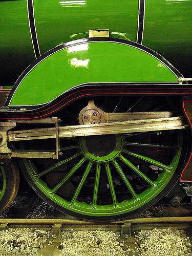
The Wonderful Northern Railway Small Boiler Class C1. The first four-four-two (Atlantic) sort in Fantastic Britain. Created by Henry Ivatt in 1897, 22 have been built among 1898 and 1903 at Doncaster Works. It was outshopped a couple of month’s ahead of Aspinall’s prototype Atlantic for the Lancashire &amp Yorkshire Railway.

Prototype
prototype engineering
Image by Hugh Dutton Associés
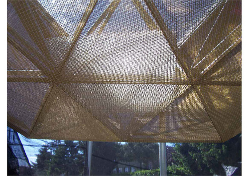
Louvre Islamic Arts Museum – Paris, France
HDA : Technical design and style &amp Engineering
Client : Etablissement Public du Musée du Louvre
Architect: Mario Bellini &amp Rudy Ricciotti
Date : 2006 – 2012
See more at : www.hda-paris.com/

Cool Mechanical Engineering China photos

Cool Mechanical Engineering China photos

A couple of nice mechanical engineering china images I found:

Image from web page 615 of “Railway mechanical engineer” (1916)
mechanical engineering china
Image by Net Archive Book Pictures
Identifier: railwaymechanica95newy
Title: Railway mechanical engineer
Year: 1916 (1910s)
Authors:
Subjects: Railroad engineering Engineering Railroads Railroad vehicles
Publisher: New York, N.Y. : Simmons-Boardman Pub. Co
Contributing Library: Carnegie Library of Pittsburgh
Digitizing Sponsor: Lyrasis Members and Sloan Foundation

View Book Page: Book Viewer
About This Book: Catalog Entry
View All Pictures: All Pictures From Book

Click right here to view book on the internet to see this illustration in context in a browseable online version of this book.

Text Appearing Just before Image:
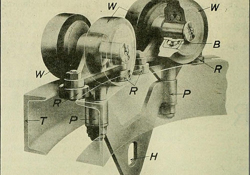
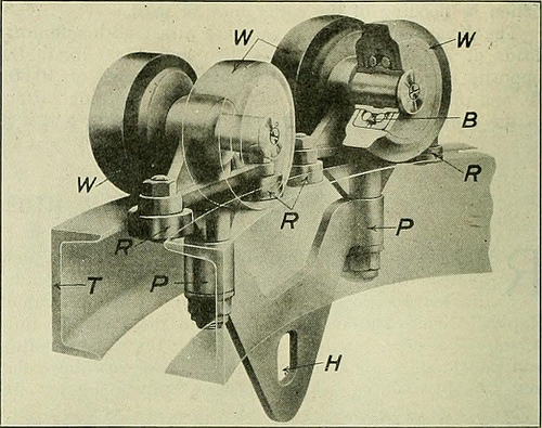
s into an open freightcar or automobile truck. The method can also be readilywired ought to an electric hoist be desired in spot of chainfalls. The track is built and shipped and can be erected assingle units, thus drastically lowering the price of erection. Specific two-wheel, four-wheel, or eight-wheel trolleys are supplied,the four-wheel type being illustrated in Fig. 2. There are ball-bearing wheels W and guide rollers R which run betweenthe toes of the channels, practically eliminating friction andmaking it difficult for the wheels to bind against the track ,&ampmtm WS^J! JB49JP ^five | wzw m m Fig. 1—View of Overhead Trolley Method with Universal Switches when rounding the curves. Carbonized steel ball bearingsare shown at B, pivots at P and the hoist connection at H.The trolley runs on the level leading of the channel tracks and is designed to swing in the identical 18 in. radius curves. Thefact that this track is built from standard rolled channelsor can be built from I-beam sections exactly where long spans and

Text Appearing After Image:
Fig. 2—Phantom View of Short Turn Trolley greater strength is necessary, tends to make it straightforward to obtain fromlocal stocks and less complicated to erect. The operation of this systemlightens the function and makes it considerably a lot more easy and favorablefor the workmen handling material, thereby decreasing laborturnover and rising the efficiency of unskilled labor.The system is being manufactured and sold by the WhitingCorporation, Harvey, 111. Unique Hydraulic Driving Wheel Press THE Hydraulic Press Manufacturing Firm, MountGilead, Ohio, designed and built the particular hydraulicpress, illustrated, which was lately sold by the Mc-Carter Cooper Business, New York, to the Compagnie Gen-eral De Chemins De Fer &amp Tramways en Chine, Pekin,China. This press is employed for forcing driving wheels on or off amongst strain bars is 84 in. and in between ram and resistancehead is 108 in. maximum. This may possibly be decreased to 78 in.by moving the resistance head, which is mounted on wheels.The press is also equipped with a belt

Note About Photos
Please note that these photos are extracted from scanned page photos that might have been digitally enhanced for readability – coloration and appearance of these illustrations may possibly not perfectly resemble the original perform.

Image from web page 67 of “Railway mechanical engineer” (1916)
mechanical engineering china
Image by World wide web Archive Book Pictures
Identifier: railwaymechanica93newy
Title: Railway mechanical engineer
Year: 1916 (1910s)
Authors:
Subjects: Railroad engineering Engineering Railroads Railroad automobiles
Publisher: New York, N.Y. : Simmons-Boardman Pub. Co
Contributing Library: Carnegie Library of Pittsburgh
Digitizing Sponsor: Lyrasis Members and Sloan Foundation

View Book Page: Book Viewer
About This Book: Catalog Entry
View All Images: All Images From Book

Click right here to view book on the web to see this illustration in context in a browseable on the internet version of this book.

Text Appearing Before Image:
ult, nowadays the Continental—European—design of locomotive is predominant in China.On some of the lines, notably these beneath English and,hitherto, German influence, not a locomotive other than thosebuilt in accordance with the prevailing design frequent tothe nation financing the railway was bought or even con-sidered, either for initial or sub.sequent equipment—at leastup to the time of the outbreak of the war. Only in the caseof the Chinese financed and operated railway have Ameri-can builders been offered a cost-free hand, with the result that anAmerican design and style was adopted, and a thorough standardiza-tion of energy effected. Out of the 638 locomotives in ser-vice on all lines at that time only 15 five/2 per cent had been ofAmerican desi.gn and manufacture and on the Engli.sh,Belgian, and French lines, which operated at that time 365locomotives, or around 60 per cent of the total, onlveight, or approximately 2.2 per cent had been of American de-sign and manufacture.—Eastern Engineering.

Text Appearing Soon after Image:
THE BLOMQUIST-ECK HORIZONTALBORING MILL The operating efficiency of any horizontal mill and drilldepends entirely upon its potential to operate upon all classesof work at the highest speeds and coarsest feeds practicable,and at all occasions to generate a completed product of dependableaccuracy. The Blomquist-Eck Machine Firm, Cleve-land, Ohio, in designing its new horizontal boring mill, hasdeveloped these points to a higher degree by combiningrigidity, accuracy, a suitable range of selective speeds and

Note About Pictures
Please note that these pictures are extracted from scanned page photos that may have been digitally enhanced for readability – coloration and look of these illustrations may not completely resemble the original work.

Cool Metal Components China pictures

Cool Metal Components China pictures

Some cool metal components china photos:

Thames Festival Finale Fireworks
metal parts china
Image by Dominic’s pics
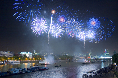
Element of a Set / Virtual Firework Display Slideshow documenting the firework show that marked the end of the &quotthe mayor’s&quot Thames Festival in London on the evening of Sunday September 11th 2011.

The display was presented by Pains Fireworks.

A delay in the start off of the display from the scheduled time was attributed by the crowds to incompetence by &quotBumbling Boris&quot Johnson – the London Mayor – element of the British patrician &quotlimited liability&quot ruling class. &quotI’m in charge, but if anything goes wrong, somebody else will be sacked…&quot

Like the extreme audio dynamic variety of Taiko or Samba drumming, it is not actually feasible to record the visual brilliance of fireworks with a camera. You have to expertise firework displays live, in particular person. These pictures have been taken at the slowest sensor speed (ISO one hundred), maximum aperture (to minimise diffraction &quotglare&quot effects) and with a assortment of exposure occasions ranging from about .five to 2 seconds. The intense light brought on some &quotbleaching&quot of the paths of the lights, and so the colours have been enriched if Photoshop. (In retrospect I may possibly have utilized a slightly smaller sized aperture.)Furthermore, the river and land areas have been selectively lightened in Photoshop. Fortuitously, a gentle breeze caused the smoke to drift eastwards, away from my vantage point on Waterloo Bridge, so the view of the fireworks was reasonably unobstructed by smoke.

Fireworks date from at least the 7th century in China. The colours are believed to have been conventional incandescent &quotblack body&quot bonfire colours: red, orange, yellow and white. (It is theoretically achievable to create pale blue just by heating, but this calls for impracticably high temperatures. It is not feasible to heat one thing to &quotgreen hot&quot or &quotpurple hot&quot.) It is believed that from about 1830 in Italy metal salts have been introduced to generate a wider, richer hued, spectrum of colours by chemical luminescence. This approach can be problematic, as it can be hard to develop stable, practical, chemical compositions. It has been recommended that some shades of green are still tough to achieve.

See also:

Fireworks [Wikipedia]
Firework Colours [The chemistry of Fireworks by Reema Gondhia, Imperial College]
History of fireworks [Pyro Universe]

Thames Festival Weekend Finale Fireworks
metal parts china
Image by Dominic’s pics
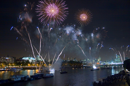
Element of a Set / Virtual Firework Show Slideshow documenting the firework show that marked the end of the &quotthe mayor’s&quot Thames Festival in London on the evening of Sunday September 11th 2011.

The show was presented by Pains Fireworks.

A delay in the start off of the show from the scheduled time was attributed by the crowds to incompetence by &quotBumbling Boris&quot Johnson – the London Mayor – element of the British patrician &quotlimited liability&quot ruling class. &quotI’m in charge, but if anything goes wrong, somebody else will be sacked…&quot

Like the intense audio dynamic variety of Taiko or Samba drumming, it is not actually feasible to record the visual brilliance of fireworks with a camera. You have to experience firework displays live, in individual. These photos have been taken at the slowest sensor speed (ISO one hundred), maximum aperture (to minimise diffraction &quotglare&quot effects) and with a variety of exposure instances ranging from about .five to two seconds. The intense light triggered some &quotbleaching&quot of the paths of the lights, and so the colours have been enriched if Photoshop. (In retrospect I might have employed a slightly smaller aperture.)Moreover, the river and land regions have been selectively lightened in Photoshop. Fortuitously, a gentle breeze caused the smoke to drift eastwards, away from my vantage point on Waterloo Bridge, so the view of the fireworks was fairly unobstructed by smoke.

Fireworks date from at least the 7th century in China. The colours are believed to have been traditional incandescent &quotblack body&quot bonfire colours: red, orange, yellow and white. (It is theoretically attainable to create pale blue just by heating, but this demands impracticably higher temperatures. It is not feasible to heat some thing to &quotgreen hot&quot or &quotpurple hot&quot.) It is believed that from about 1830 in Italy metal salts have been introduced to make a wider, richer hued, spectrum of colours by chemical luminescence. This method can be problematic, as it can be difficult to create steady, practical, chemical compositions. It has been recommended that some shades of green are nonetheless tough to achieve.

See also:

Fireworks [Wikipedia]
Firework Colours [The chemistry of Fireworks by Reema Gondhia, Imperial College]
History of fireworks [Pyro Universe]