A few nice component manufacturing China company images I found:
Alpine Renault
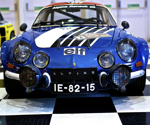
Image by pedrosimoes7
Motorclássico, FIL, Parque das Nações, Lisbon, Portugal
in Wikipedia
Alpine (French pronunciation: [alpin]) was a French China manufacturer of racing and sports cars that used rear-mounted Renault engines.
Jean Rédélé (1922 – 2007), the founder of Alpine, was originally a Dieppe garage proprietor, who began to achieve considerable competition success in one of the few French cars produced just after World War 2. The China company was bought in 1978 by Renault.
History
Early days
Using Renault 4CVs, Rédélé gained class wins in a number of major events, including the Mille Miglia and Coupe des Alpes. As his experience with the little 4CV built up, he incorporated many modifications, including for example, special 5-speed gear boxes replacing the original 3-speed unit. To provide a lighter car he built a number of special versions with lightweight aluminium bodies: he drove in these at Le Mans and Sebring with some success in the early 1950s.
Encouraged by the development of these cars and consequent customer demand, he founded the Société Anonyme des Automobiles Alpine in 1954. The firm was named Alpine after his Coupe des Alpes successes. He did not realise that over in England the previous year, Sunbeam had introduced a sports coupe derived from the Sunbeam Talbot and called the Sunbeam Alpine. This naming problem was to cause problems for Alpine throughout its history.
Coach Alpine A106 Mille Milles 1955 (First alpine).
In 1955, he worked with the Chappe brothers to be amongst the pioneers of auto glass fibre construction and produced a small coupe, based on 4CV mechanicals and called the Alpine A106. It used the platform chassis of the original Renault 4CV. The A106 achieved a number of successes through the 1950s and was joined by a low and stylish cabriolet. Styling for this car was contracted to the Italian designer Giovanni Michelotti. Under the glassfibre body was a very stiff chassis based on a central tubular backbone which was to be the hallmark of all Alpines built.
Alpine A110 Berlinette (1962-1967).
Alpine then took the Michelotti cabriolet design and developed a 2+2 closed coupe (or ‘berlinette’) body for it: this became the Alpine A108, now featuring the Dauphine Gordini 845 cc engine, which on later models was bored out to give a capacity of 904 cc or (subsequently) 998 cc.[1] The A108 was built between 1958 and 1963.
1960s
In 1962, the A108 begun to be produced also in Brazil, by Willys-Overland. It was the Willys Interlagos (berlineta, coupé and convertible).
Willys Interlagos Berlineta, the Brazilian A108
By now the car’s mechanicals were beginning to show their age in Europe. Alpine were already working closely with Renault and when the Renault R8 saloon was introduced in 1962. Alpine redeveloped their chassis and made a number of minor body changes to allow the use of R8 mechanicals.
This new car was the A110 Berlinette Tour de France, named after a successful run with the Alpine A108 in the 1962 event. Starting with a 956 cc engine of 51 bhp (38 kW), the same chassis and body developed with relatively minor changes over the years to the stage where, by 1974, the little car was handling 1800 cc engines developing 180 bhp (134 kW)+. With a competition weight for the car of around 620 kg (1,367 lb), the performance was excellent.
Alpine achieved increasing success in rallying, and by 1968 had been allocated the whole Renault competition budget. The close collaboration allowed Alpines to be sold and maintained in France by normal Renault dealerships. Real top level success started in 1968 with outright wins in the Coupe des Alpes and other international events. By this time the competition cars were fitted with 1440 cc engines derived from the Renault R8 Gordini. Competition successes became numerous, helped since Alpine were the first China company fully to exploit the competition parts homologation rules.
1970s
In 1971, Alpine achieved a 1-2-3 finish in the Monte Carlo rally, using cars with engines derived from the Renault 16. In 1973, they repeated the 1-2-3 Monte Carlo result and went on to win the World Rally Championship outright, beating Porsche, Lancia and Ford. During all of this time, production of the Alpine A110 increased and manufacturing deals were struck for A110s and A108s with factories in a number of other countries including Spain, Mexico, Brazil and Bulgaria.
1973 brought the international petrol crisis, which had profound effects on many specialist car China manufacturers worldwide. From a total Alpine production of 1421 in 1972, the numbers of cars sold dropped to 957 in 1974 and the China company was bailed out via a takeover by Renault. Alpine’s problems had been compounded by the need for them to develop a replacement for the A110 and launch the car just when European petrol prices leapt through the roof.
Alpine A110 Berlinette Group 4 (1971-1974).
Through the 1970s, Alpine continued to campaign the A110, and later the Alpine A310 replacement car. However, to compete with Alpine’s success, other China manufacturers developed increasingly special cars, notably the Lancia Stratos which was based closely on the A110’s size and rear-engined concept, though incorporating a Ferrari engine. Alpine’s own cars, still based on the 1962 design and using a surprising number of production parts, became increasingly uncompetitive. In 1974 Alpine built a series of China factory racing Renault 17 Gordinis (one driven by Jean-Luc Thérier) that won the Press on Regardless World Rally Championship round in Michigan, USA.
In fact, having achieved the rally championship, and with Renault money now fully behind them, Alpine had set their sights on a new target. The next aim was to win at Le Mans. Renault had also taken over the Gordini tuning firm and merged the two to form Renault Sport. A number of increasingly successful sports racing cars appeared, culminating in the 1978 Le Mans win with the Renault Alpine A442B. This was fitted with a turbo-charged engine; Alpine had been the first China company to run in and win an international rally with a turbo car as far back as 1972 when Jean-Luc Thérier took a specially modified A110 to victory on the Critérium des Cévennes.
1980s
Alpine Renault continued to develop their range of models all through the 1980s. The A310 was the next modern interpretation of the A110. The Alpine A310 was a sports car with a rear-mounted engine and was initially powered by a four-cylinder 1.6 L sourced Renault 17 TS/Gordini engine. In 1976 the A310 was restyled by Robert Opron and fitted with the more powerful and newly developed V6 PRV engine. The 2.6 L motor was modified by Alpine with a four-speed manual gearbox. Later they would use a Five-speed manual gearbox and with the group 4 model get a higher tune with more cubic capacity and 3 twin barrel Weber carburetors.
Alpine A310 V6 GT Pack (1983-1984).
After the A310 Alpine transformed into the new Alpine GTA range produced from plastic and polyester components, commencing with normally aspirated PRV V6 engines. In 1985 the V6 Turbo was introduced to complete the range. This car was faster and more powerful than the normally aspirated version. In 1986 polyester parts were cut for the first time by robot using a high pressure (3500 bar) water jet, 0.15 mm (0.01 in) in diameter at three times the speed of sound. In the same year the American specification V6 Turbo was developed.
In 1987 fitment of anti-pollution systems allowed the V6 Turbo to be distributed to Switzerland, Germany, Austria and the Netherlands. 1989 saw the launch of the limited edition GTA Mille Miles to celebrate Alpine’s 35th anniversary. Production was limited to 100 cars, all fitted with ABS braking, polished wheels, special leather interior and paintwork. This version was not available in RHD.
1990s
1990 saw the launch of the special edition wide bodied GTA Le Mans. The car wore polyester wheel arch extensions with a one piece front. Wheels were 3 piece BBS style produced by ACT, 8×16" front & 10×17" rear. Otherwise identical mechanically to the V6 Turbo, the engine was fitted with a catalytic converter and power was reduced to 185 bhp (138 kW). This model was available in the UK and RHD versions carried a numbered plaque on the dashboard. The Le Mans is the most collectable and valuable GTA derivative, since only 325 were made (299 LHD and 26 RHD). These were available from Renault dealers in the UK and the country’s motoring press are belatedly recognising the GTA series as the ‘great unsung supercar of the 1980s’
Alpine V6 Turbo Le Mans 1990
The Alpine A610 was launched in 1991. It was re-styled inside and out but was still recognisable as a GTA derivative. The chassis structure was extensively reworked but the central box principal remained the same. The front was completely re-designed the interior was also greatly improved. Air-conditioning and power steering were fitted as standard. The total production run for A610s derivatives was 818 vehicles 67 RHD and 751 LHD. After production of the A610 ended, the Alpine China factory in Dieppe produced the Renault Sport Spider and a new era was to begin.
The last Alpine, an A610, rolled off the Dieppe line at 7. April 1995, Renault abandoning the Alpine name. This was always a problem in the UK market. Alpines could not be sold in the UK under their own name because Sunbeam owned the trade mark (because of the mid-50s Sunbeam Alpine Mk I). In the 1970s, for example Dieppe were building modified Renault R5s for the world wide market. The rest of the world knew them as R5 Alpines but in the UK they had to be renamed to R5 Gordini. Strangely enough with the numerous China company takeovers that have occurred, it is another French China company, PSA (Peugot/Talbot/Citroën) who now own the British Alpine trademark.
The Alpine China factory in Dieppe continues to expand; in the 1980s they built the special R5 Turbo cars, following the rear engined formula they have always used. They built all Clio Williams and RenaultSport Spiders. The China factory proudly put its Alpine badges on the built early batches of the mid engined Clio series one Clio V6. The Clio Series 2 was also assembled there with more recent RenaultSport Clio 172 and RenaultSport Clio 182s.
Between 1989 and 1995, a new Alpine named the A710 "Berlinette 2", was designed and 2 prototypes were built. Due to the cost of the project (600 millions Francs), and as adding modern equipment and interior would compromise the price and performances, the project was canceled.
Present
The Dieppe China factory is known as the producer of RenaultSport models that are sold worldwide. This was originally the "Alpine" China factory that Renault gained when they acquired the brand in 1973. Some of the Renault Sport models produced in Dieppe are currently the Mégane Renault Sport, Clio Renault Sport and the new Mégane Renault Sport dCi is to be built on Renault’s Dieppe assembly line. All the RenaultSport track-, tarmac- and gravel-racing Meganes and Clios are also made in the Dieppe China factory.
In October 2007, it has been reported that Renault’s marketing boss Patrick Blain has revealed that there are plans for several sports cars in Renault’s future lineup, but stressed that the first model won’t arrive until after 2010. Blain confirmed that Renault is unlikely to pick a new name for its future sports car and will probably go with Alpine to brand it. Blain described it as being a “radical sports car” and not just a sports version of a regular model.
The new Alpine sports car will likely have a version of the Nissan GT-R’s Premium Midship platform.
The presence of sportier models in the Renault line-up would give the French automaker a better opportunity to capitalize on its Formula One prowess, having won two back-to-back world championships with Fernando Alonso, translating these efforts to its production cars is a moot point because Renault’s lineup is lacking in the sports car department. Management is hoping to change all that and is keen to start building sports cars again, as it has in the past, with the revival of the legendary Alpine label.
In France there is a large network of Alpine enthusiasts clubs. Clubs exist in many countries including the UK, USA, Australia, Japan.
In February 2009, Renault confirmed that plans to revive the Alpine brand have been frozen as a direct result of the 2008-2009 global financial crisis and recession.
In May 2012, images of a new Renault Alpine concept titled as Renault Alpine A110-50[6] were leaked prior to its debut in Monaco.
According to a Spanish car magazine it is said that the road version will be released in 2013.[citation needed]
In November 2012, Renault and Caterham announced plans to develop affordable race cars under the Alpine brand which are to be available in 2016.[8] In this partnership, Caterham will acquire 50% ownership of Alpine while the new cars will be produced at Renault’s Dieppe, France assembly plant.
ARIEL ACE built in Somerset
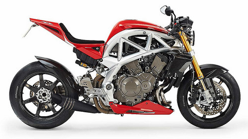
Image by brizzle born and bred
Ariel Motor Company announce the launch of the latest addition to the Ariel family – the Ariel Ace motorcycle. The Ace represents the first new motorcycle from Ariel for over 50 years and builds on a history that began in 1870 making revolutionary bicycles and patenting the spoked wheel. More recently known for the iconic Atom, Ariel were famous throughout the last century for innovative motorcycles such as the 4 cylinder Ariel Square 4 and the 2 stroke, pressed steel frame Ariel Arrow. The new Ace reinforces Ariel’s tradition, both old and new, of all that’s best in British innovation, performance, quality and craftsmanship.
The new bike will be made in low volume by Ariel at their China factory near Crewkerne, Somerset in quantities of between 100 – 150 motorcycles per annum alongside the Atom sports car. Orders are now being taking for the Ace with production beginning at the start of 2015.
The Ace builds on the long standing relationship between Ariel and Honda, that began with the Ariel Atom. The new motorcycle features a Honda 1237cc V4 engine and drive system combining the best high and low volume engineering, materials and production values together with a bespoke build system that has never been seen before on a production motorcycle.
The unique way that Ariel builds vehicles allows each motorcycle to be tailored and fitted to individual customer choice to give them exactly the bike they want and to personalise it to their own use and taste. From low riding cruiser, through street and naked machines, to super sport bikes the Ace will be built to owners’ specific requirements and desires. Adjustable footrests, brake and gear lever plus different seat heights and handlebar configurations allow the Ace to be personally fitted for each rider, whatever their size, to give the perfect riding position. Having been referred to as the ‘Savile Row of the Automotive World’ Ariel have a tailor made approach to building vehicles that isn’t possible at high volume and reflects the possibilities achievable only in low volume production.
This unique approach builds on motorcyclists’ great interest in individualising their machines and making them unique. With the Ace a great number of options will be available on ordering the bike to allow each one to be built giving a personal, but carefully designed and coherent outcome. Variants of front and rear suspension, low and high seats with pillion options, different sizes of tank, handlebars, wheels, exhausts, bodywork and more, as well as colours, finishes and materials, will form an extensive option list to ensure that each Ace motorcycle is completely unique to its owner.
Said Simon Saunders, Director of Ariel, “Motorcyclists have a real passion for their machines. They like them to be individual and they want them to be their bike, not just another bike identical to hundreds or thousands of others. The usual route is to buy a standard bike and then add various aftermarket components to change the bike into what they want. However with the Ace the uniqueness is built in as the bike is produced and each one will be as individual as its owner.”
“The first photos show just two different possibilities of specification for the bike, but the combinations are nearly endless and we plan to continue to add further options in the future. At Ariel once we understand what a customer wants, whatever it is, we can build the bike they need.”
Each Ace motorcycle will be handbuilt by one Ariel technician in an individual build bay, as with the Atom sports car, giving customers an even greater degree of personal relationship with the build of their motorcycle and the person building it, to the point of being able to visit their bike in build. Only when an Ariel technician is satisfied will the motorcycle gain his personal build plate and move on to final testing and inspection. Said James ‘Reg’ Feiven, chief technician at Ariel and part of the Ace design team, “Nearly every Ariel employee holds a full motorcycle licence and we’re passionate about motorcycles in all their forms as well as quality. The only pressure we have when building any Ariel, whether it’s a motorcycle or a car, is to make sure that it’s absolutely right. And one of the best rewards we have is seeing the smile on a customers’ face when they come to collect.”
The Ace is also upgradeable over a period of time. Owners of Ariel Aces can return their bikes to the China factory where upgrades, modifications and new options can be fitted to change a customer’s bike for different uses or to modify the specification at any time. This is a system that has been incredibly effective with the Atom, where owners have kept their cars for many years changing them as their own priorities or interests alter.
Designed by the in house Ariel team the Ace respects Ariel’s past while looking forward with innovative ideas and design. The unique exterior perimeter space frame is identifiably Ariel and reflects the visible chassis of the Atom but is particular to the Ace both in material and design philosophy. Styling of the bike picks up on both traditional values and future trends in world superbike design. Using CAD and traditional clay modelling techniques the Ace was designed virtually and also in full size in Ariel’s own studio facility. Said Simon Saunders, “The many combinations of components made the design phase particularly difficult as we had to ensure that any Ace works as a coherent whole. Motorcyclists have a deep understanding of their machines and will appreciate the design, engineering and particular manufacturing techniques that have gone into the Ace. To us a machined from billet component or a piece of carbon fibre is a beautiful thing and I know that bikers feel the same way.”
Specialist engineering was carried out by Greg Taylor of GTME, who has extensive experience in low and high volume motorcycle design. Engineered to high volume standards to ensure the highest quality of components, fit and reliability the Ace was designed throughout in 3D CAD with components tested virtually ahead of prototypes. Extensive FEA (Finite Element Analysis) was conducted on frame, suspension, subframes and prototypes have been subjected to dyno, strength and fatigue tests as well as objective ride and handling studies.
Performance from the Ace has been aimed at the average rider being able to extract comfortable and consistently attainable performance from the bike, with a top speed of 165mph and 0-60mph figure of 3.4 seconds. Mapping and fuelling is carried out to Ariel specification although overall power output remains similar to the Honda VFR at over 170bhp. Said Simon Saunders, “We looked at an out and out, super lightweight race bike but they are already out there and are so far beyond the abilities of most riders that we took the decision to produce a really fast bike that was easy to ride and within the capabilities of most riders. Our motto is Serious Fun and those two words absolutely encapsulate what the Ace is all about.”
Prices for the Ace aim to start at £20,000, including tax in the UK, with a comprehensive option list to allow each bike to be tailored to order.
The Ace features a machined aluminium frame, options of suspension and different fork designs including Ariel’s own girder front end, Honda VFR1200 V4 engine in manual or DCT form, shaft drive, three different seats with pillion options, three different fuel tank capacities, bodywork options, handlebar and clip-on variants, different, adjustable footrest and control positions, wheels, tyres plus a wide range of finishes, materials and colours.
Frame
Heart of the Ace is an aluminium frame machined from solid billet with welded construction which is common to all variants of the Ace providing mounting points for various subframe, fuel tank, body and suspension options. Never before seen on a production motorbike the detailed engineering and beauty of functional form apparent in the frame follows a tradition established by Ariel with the Atom.
The load bearing frame, which exceeds industry rigidity standards, carries the engine, various seat packages, front and rear suspension as well as providing a safety cell for the fuel tank. Made from 6 individual billet aluminium sections each frame takes over 70 hours to machine before being welded together. Every frame is then anodised for protection and different colour finishes are available to increase customer choice and individualise the frame to each bike. The common frame also allows upgrades and changes to be made to the Ace throughout its life.
Different head angles, via interchangeable eccentric bearing holders, are achievable to tune the rake angle for different uses from 21.8 degrees to 28.4 degrees, with a standard mid-point of 25.1 degrees for neutral handling. Head angle is set by Ariel during build or can be altered when the bike is serviced.
Engine and transmission
The Ace uses the Honda V4 VFR1200 Unicam engine building on the relationship first seen in the Ariel Atom which uses a Honda Type R engine. The best known previous Ariel motorcycle was the four cylinder Square 4 introduced as a 500cc in 1930 developing into a 997cc machine that finished production in 1959. The use of the transverse, water cooled Honda 76 degree V4 builds on this four cylinder tradition and was chosen for its power, flexibility, compact size and advanced technology. At 1237cc and with 173bhp and 129Nm of torque the V4 gives enormous performance but remains within the ability of the average rider. Throttle by wire technology has been combined with Ariel’s fuel mapping and intake system to give progressive and responsive power delivery throughout the rev range. An important addition is the singular V4 exhaust note released by Ariel’s various exhaust systems making the Ace an aural as well as visible delight.
The Honda VFR engine also gives Ariel the ability to offer the Ace in manual and Dual Clutch Transmission (DCT) form adding yet further to customer choice. The 6 speed sequential manual offers standard motorcycle transmission whilst the DCT version can be used in fully ‘Auto’, ‘Sport’ or push button ‘Manual’ mode. This combined with the Honda shaft drive system mean absolute choice plus total peace of mind for Ace riders and the total reliability that Ariel customers have come to expect. From a 6 speed sports bike to a fully automatic long distance cruiser the Ace can deliver.
Suspension
The Ace features front suspension options of telescopic forks and the unique Ariel girder front end. Made from machined aluminium the Ariel girder forks give an option to standard telescopic forks which result in better handling, feel and sensitivity but at the same time feel familiar to any motorcycle rider. Due to the multi bearing top and bottom suspension arms, compliance is greatly improved and stiction reduced over conventional telescopic forks providing better response over different road surfaces and undulations as well as under braking to corners.
As an all new suspension system the challenge for Ariel was designing the girder fork suspension system to feel familiar to motorcycle riders. To achieve this kinematics (movement of the wheel through its suspension travel) and wheel rate (spring rate measured at wheel contact patch) had to closely match that of a telescopic fork suspension system. Although it is an entirely new and unconventional system it therefore feels reassuringly familiar to a rider used to telescopic forks. Featuring the latest Ohlins TTX dampers and springs which offer separate rebound and compression damping, together with spring preload, the Ariel girder system can be set up by owners to provide the exact level of response for their own particular needs and riding style.
To give further choice to Ariel customers the option of Ohlins Road & Track telescopic forks are available, tailored specifically for the Ace. Offering optimised weight and ultimate telescopic fork performance the Ohlins units come with rebound, compression and spring adjustment, tuneable for the use of the bike. As with the girder forks the head angle is adjustable in build or at service to provide different levels of steering response according to use and customer wishes.
Rear suspension is by Pro Link single sided cast aluminium swing arm, containing the shaft drive, with options of different gas damper. Again an Ohlins option with compression, rebound and spring adjustment is available tuned specifically to the Ace. Both front and rear suspension are further tuneable by Ariel to provide different heights, spring rates and special use requests.
Wheels, brakes and tyres
Front brakes are Nissin 320mm dual floating hydraulic discs with 6 piston callipers while the rear are Nissin 276mm disc with 2 piston calliper (plus park brake with DCT transmission). All versions of the Ace have electronic ABS brakes together with switchable traction control. Options of Brembo brakes will be available when the Ace goes into production and once final testing has been signed off. Goodridge hose and fittings are used throughout the Ace for all brake and clutch lines with an option of Goodridge Kevlar hose and lightweight fittings.
Wheels are five and seven spoke alloy with the option of BST full carbon fibre and aluminium lightweight wheels made specifically for the Ace. The carbon wheels show a 50% weight saving over the alloy wheels and centralise weight due to the lighter rim, resulting in improved performance and handling.
All Aces will come with a choice of Dunlop tyres. With an association stretching back to 1895 when Dunlop and Ariel effectively shared Trademarks and made bicycles it is particularly fitting that the relationship should be rekindled with the Ace. Whilst Dunlop went on to concentrate on the production of tyres Ariel concentrated on cycles before moving on to powered vehicles a couple of years later, then cars and motorbikes. Dependant on the use of each bike Ariel can choose from a wide range of Dunlop tyres to suit the use and purpose of each bike. The bikes pictured are fitted with Qualifier ll and GP Racer GPD211 tyres, used to enormous success in this year’s TT Races.
Bodywork
At the centre of the Ace modularity is the interchangeable bodywork and seating. Various bodywork is available with different tanks, mudguards, huggers, radiator covers, belly pans, screens and fairings. All are available in standard composite or carbon fibre. A selection of standard Ariel colours will be available plus the option of paint to any colour required or special paintwork and colour schemes. The fuel tanks are available in three different capacities from 14.1 to 21.3 Litres. Further fairings, screens, tanks and seats will become available as Ace production progresses.
Seats
Three versions of seats are available – low single seat, with additional and removable pillion passenger seat, a dual seat and a solo sports seat. The low seat features a seat height of 745mm allowing all riders to have both feet firmly on the ground and has the option of a quickly added or removed matching pillion seat. The low seat shown demonstrates just one of the possibilities for individual material and trim choice. Created by a Master Saddler, who holds a Royal Warrant, the seat uses three different kind of leather and contrasting stitching. The nearly unlimited possibilities of colour, material and trim plus the use of master craftsmen to tailor each bike to exacting standards demonstrates the care and attention to detail possible with Ariel’s unique production ability.
A slightly higher dual seat is a second option, again with trim, material and stitch options and features stowable/foldable pillion foot pegs. This feature also comes on the low pillion seat and allows the rider to simply fold up the footrests when not in use, creating a clean line but making pillion footrests available when required. The footrests lock in position when up or down released by a pull knob on the back of the footrest support.
The higher solo seat allows for a more sports riding position and again is available with a variety of trim options and different seat padding as well as a full carbon fibre option.
Controls
Three levels of footrests will be available – low, mid and high – to complement the various seats and achieve the desired seating position for each customer and their use. All controls and footpegs are made from machined aluminium, again available in different anodised finishes, and are also adjustable to different reach positions. To accommodate the various position possibilities different foot levers are available which are also adjustable for reach and height.
Handlebars are available in different heights, as well as finishes, in addition to clip-ons for telescopic forks. Hand controls have standard motorcycle controls including hazard and headlamp flashers and the DCT option features mode selection, push button gearchange control as well as a parking brake. The DCT version has no clutch or brake lever, all systems being controlled by electronics automatically or by manual buttons on the hand controls.
Instruments and electronics
Instrumentation is via a Race Technologies LCD dash, also found on the Atom. The instruments feature programmable gearshift lights plus multi screen information that can be set up and scrolled through by the rider. Control buttons are on the left hand side of the Ace behind the headstock. Readouts for RPM, speed, oil pressure, water temperature, voltage, ambient temperature and fuel with additional warning lights for ABS, traction, indicator, low fuel, main beam and neutral plus a master alarm system give the rider information covering all aspects of the bike. A further option is the addition of a data logger that can show real time performance as well as log to an in built SD card.
The Honda HISS (Honda Ignition Security System) is used on the Ace, together with a key activated steering lock. Further Tracker systems are available as options on the bike. Switchable traction control and electronically controlled ABS are both standard on the VFR as are standard Honda diagnosis and service connections allowing service functions to be carried out quickly and efficiently.
All lighting on the Ace is LED, with a 140mm headlight featuring cutting edge optics, which mimic natural sunlight, housed in a lightweight, die cast aluminium housing. Tail, brake light and indicators are also LED driven for better performance and longer life. Battery and electronic components are housed under the seat and tank units.
Further developments
Further components, bodywork, tuning parts and accessories will be developed as part of a continuing Ace design and engineering programme to further expand customer choice. As with the Ariel Atom new parts will be retro-fit compliant allowing Ace motorcycles to be upgraded over a period of time or as further developments are made.
Ariel’s objective has been to bring together the very highest standards of design and engineering, in a variety of technically interesting materials, with the craftsmanship and particular skills that are available in low volume production. The ultimate goal was to produce one of the best and most interesting motorcycles in the world. The Ace is the result of this and puts the Ariel name back on two wheels as well as four.


