Visit www.datron.com for more info. This video shows a German-engineered M8Cube machining center milling a mold for a the production of a radio-controlled Qu…
Video Rating: 0 / 5
Rapid Prototyping China
Visit www.datron.com for more info. This video shows a German-engineered M8Cube machining center milling a mold for a the production of a radio-controlled Qu…
Video Rating: 0 / 5


Irvine, California (PRWEB) August 15, 2014
Laguna Tools has recently announced the introduction of the NEW SmartShop 3 CNC China Machining Center, developed to introduce an advanced technological platform for the next generation of Laguna CNC China Machinery.
The machine features a new computer-designed frame that includes an all-welded structural steel base to ensure the accuracies and cut qualities that have remained key characteristics of the SmartShop CNC product line. Additionally, the new SmartShop’s structural steel gantry is internally reinforced, permitting the use of a variety of machining package options. Finally, a gantry-mounted carousel tool changer was added to reduce tool change times; an especially relevant feature on large table format machines.
The fluid movement of the Laguna SmartShop 3 CNC can be contributed to the precise machining of frame components, precision-ground contour guide rails in all axes, and top-notch “closed-loop” servos and drives by the innovative OSAI Open machine controller.
Movements on both X and Y axes are achieved with world-class helical rack-and-pinions driven by precision planetary drive systems. Z-axis motion is controlled by a precision-ground ball screw and the precision planetary drive system. Another benefit of using a planetary drive system is that it permits Laguna China Engineering to mount the guide rails lower on the side of the base frames. This results in the tables easier for the machine operator to load and unload.
Included as a standard feature on the new SmartShop 3 models is a Laguna Tools designed “pod-ready” vacuum table, which combines with six vacuum zones, providing unbeatable fixturing possibilities. Part locator pins and extra -large vacuum ports have been included specifically for panel processing needs.
Another new innovation for the Laguna SmartShop 3 is the inclusion of the new OSAI Open machine control system. It includes a touch screen PC to provide a user-friendly GUI (Graphic User Interface). This also allows the machine to be connected to the local area network (LAN), making file transfers a breeze, while maintaining the reliability of a leading industrial China CNC machine controller.
“I gave Laguna China Engineering a challenge to develop the next generation SmartShop CNC,” said Torben Helshoj, President of Laguna Tools. “The design requirements were quite simple. It had to build on the tremendous success the SmartShop CNCs have enjoyed. It had to be a platform that would allow us to expand the CNC product line in a variety of directions (into the foreseeable future). It had to have the best vacuum table in the industry. It had to have a “full-feature” machine controller that was still easy-to-learn and easy-to-use and that could handle multi-axis applications. And, it had to be affordable. I am extremely pleased with the outcome of this project, the Laguna SmartShop 3! It truly expresses our company spirit, ‘Thriving on Innovation.’ I think the future is very bright for this product.”
The Laguna SmartShop 3 is available in a variety of standard table sizes including 4 x 4, 4 x 8, 5 x 10, and 5 x 12. Custom table sizes and machining packages can also accommodate special application needs.
ABOUT LAGUNA TOOLS:
Laguna Tools is a global leader in affordable CNC technology for the wood, plastic, non-ferrous, and aerospace industries. The privately owned company is based in Irvine, CA, and has a near-31-year history of product innovation. The company prides itself in sourcing the very finest machine components worldwide to ensure that Laguna Tool products offer performance second-to-none.
Laguna Tools products are sold worldwide both direct to the consumer as well as through a network of authorized Laguna Tools dealers.
For more information, please visit http://www.lagunatools.com.
[youtube http://www.youtube.com/watch?v=CqePrbeAQoM&fs=1&rel=0]

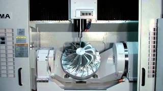
http://www.okuma.com/americas The MU-V Series provides the power of process-intensive China machining and high-speed, high-accuracy cutting through the combination…
[youtube http://www.youtube.com/watch?v=vf5VdQzuSjQ&fs=1&rel=0]
How to build low cost home made CNC mill.
Video Rating: 4 / 5
Milling Cnc on eBay:
[wprebay kw=”milling+cnc” num=”0″ ebcat=”-1″]
[wprebay kw=”milling+cnc” num=”1″ ebcat=”-1″]
[wprebay kw=”milling+cnc” num=”2″ ebcat=”-1″]

Sagrada Família, Gaudi, Barcelona

Image by F.d.W.
Sagrada Família, Gaudi, Barcelona
This is a ‘composite’ of 100 pictures 🙂
The Basílica i Temple Expiatori de la Sagrada Família (English: Basilica and Expiatory Church of the Holy Family; Spanish: Basílica y Templo Expiatorio de la Sagrada Familia), commonly known as the Sagrada Família (Catalan pronunciation: [səˈɣɾaðə fəˈmiɫiə]), is a large Roman Catholic church in Barcelona, Catalonia, Spain, designed by Catalan architect Antoni Gaudí (1852–1926). Although incomplete, the church is a UNESCO World Heritage Site,[5] and in November 2010 Pope Benedict XVI consecrated and proclaimed it a minor basilica,[6][7][8] as distinct from a cathedral which must be the seat of a bishop.
Though construction of Sagrada Família had commenced in 1882, Gaudí became involved in 1883,[5] taking over the project and transforming it with his architectural and engineering style—combining Gothic and curvilinear Art Nouveau forms. Gaudí devoted his last years to the project, and at the time of his death at age 73 in 1926, less than a quarter of the project was complete.[9] Sagrada Família’s construction progressed slowly, as it relied on private donations and was interrupted by the Spanish Civil War—only to resume intermittent progress in the 1950s. Construction passed the midpoint in 2010 with some of the project’s greatest challenges remaining[9] and an anticipated completion date of 2026—the centennial of Gaudí’s death.
The basílica has a long history of dividing the citizens of Barcelona—over the initial possibility it might compete with Barcelona’s cathedral, over Gaudí’s design itself,[10] over the possibility that work after Gaudí’s death disregarded his design,[10] and the recent possibility that an underground tunnel of Spain’s high-speed rail link to France could disturb its stability.[11]
Describing Sagrada Família, art critic Rainer Zerbst said "it is probably impossible to find a church building anything like it in the entire history of art"[12] and Paul Goldberger called it "the most extraordinary personal interpretation of Gothic architecture since the Middle Ages."[13]
en.wikipedia.org/wiki/Sagrada_Fam%C3%ADlia
Background[edit source]
The Basilica of the Sagrada Família was the inspiration of a Catalan bookseller, Josep Maria Bocabella, founder of Asociación Espiritual de Devotos de San José (Spiritual Association of Devotees of St. Joseph).[14] After a visit to the Vatican in 1872, Bocabella returned from Italy with the intention of building a church inspired by that at Loreto.[14] The crypt of the church, funded by donations, was begun 19 March 1882, on the festival of St. Joseph, to the design of the architect Francisco de Paula del Villar, whose plan was for a Gothic revival church of a standard form.[14] Antoni Gaudí began work on the project in 1883. On 18 March 1883 Villar retired from the project, and Gaudí assumed responsibility for its design, which he changed radically.[14]
Construction[edit source]
Newly constructed stonework at the Sagrada Família is clearly visible against the stained and weathered older sections.
On the subject of the extremely long construction period, Gaudí is said to have remarked: "My client is not in a hurry."[15] When Gaudí died in 1926, the basilica was between 15 and 25 percent complete.[9][16] After Gaudí’s death, work continued under the direction of Domènec Sugrañes i Gras until interrupted by the Spanish Civil War in 1936. Parts of the unfinished basilica and Gaudí’s models and workshop were destroyed during the war by Catalan anarchists. The present design is based on reconstructed versions of the plans that were burned in a fire as well as on modern adaptations. Since 1940 the architects Francesc Quintana, Isidre Puig Boada, Lluís Bonet i Gari and Francesc Cardoner have carried on the work. The illumination was designed by Carles Buigas. The current director and son of Lluís Bonet, Jordi Bonet i Armengol, has been introducing computers into the design and construction process since the 1980s. Mark Burry of New Zealand serves as Executive Architect and Researcher. Sculptures by J. Busquets, Etsuro Sotoo and the controversial Josep Subirachs decorate the fantastical façades.
The central nave vaulting was completed in 2000 and the main tasks since then have been the construction of the transept vaults and apse. As of 2006, work concentrated on the crossing and supporting structure for the main tower of Jesus Christ as well as the southern enclosure of the central nave, which will become the Glory façade.
Construction status[edit source]
Sagrada Família’s roof under construction (2009)
One projection anticipates construction completion around 2026, the centennial of Gaudí’s death—while the project’s information leaflet estimates a completion date in 2028, accelerated by additional funding from visitors to Barcelona following the 1992 Barcelona Olympics.
Computer-aided design technology has been used to accelerate construction of the building, which had previously been expected to last for several hundred years, based on building techniques available in the early 20th century.[citation needed] Current technology allows stone to be shaped off-site by a CNC milling machine, whereas in the 20th century, the stone was carved by hand.[17]
In 2008, some renowned Catalan architects advocated a halt to construction,[18] to respect Gaudí’s original designs, which, although they were not exhaustive and were partially destroyed, have been partially reconstructed in recent years.[19]
A 2010 exhibition, Gaudí Unseen, Completing La Sagrada Família at the German Architecture Museum, Frankfurt am Main, describes the current construction methods and future plans for the Sagrada Família.[19]
AVE tunnel[edit source]
On 26 March 2010, the Ministry of Public Works of Spain (Ministerio de Fomento) began constructing an AVE (high-speed train) tunnel beneath the centre of Barcelona, saying the project poses no risk to the church.[20][21] Project engineers and architects disagreed, saying there was no guarantee that the tunnel would not affect the stability of the building. The Board of the Sagrada Família (Patronat de la Sagrada Família) and the neighborhood association AVE pel Litoral (AVE by the Coast) had led a campaign against this route of the Tunnel Sants – La Sagrera for the AVE, without success.
In October 2010, the tunnel boring machine reached the church underground under the location of the building’s principal façade.[20] A few months later, the tunneling machine reached its endpoint. No damage to the Sagrada Família has been reported to date.
Trains were scheduled to start running in December 2012, when the installation of railway tracks, overhead wires and signalling is completed. ADIF intends to embed the rails into an elastic material to dampen vibrations, according to the system Edilon.[22]
the future of architecture is happening now in a Chilterns farm
I first visited five years ago, while a student at the Royal College of Art, when we made use of the farm's CNC-milling machine to build a plywood pavilion from reclaimed Olympic hoardings. Since then, the place has seen groups of students come and go, …
Read more on The Guardian (blog)
Most popular cnc China milling center eBay auctions:
[wprebay kw=”cnc+milling+center” num=”0″ ebcat=”-1″]
[wprebay kw=”cnc+milling+center” num=”1″ ebcat=”-1″]
[wprebay kw=”cnc+milling+center” num=”2″ ebcat=”-1″]
A few nice brass precision turned components China images I found:
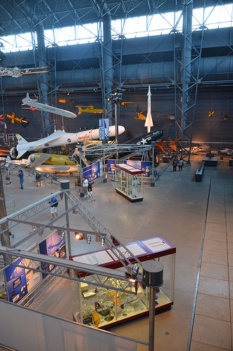
Steven F. Udvar-Hazy Center: Space exhibit panorama (misc)

Image by Chris Devers
Uploaded by Eye-Fi.
Steven F. Udvar-Hazy Center: Space exhibit panorama (misc)
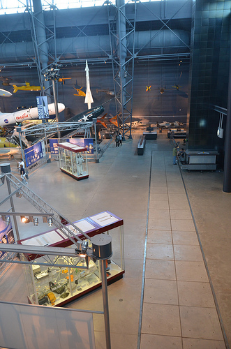
Image by Chris Devers
Uploaded by Eye-Fi.

[youtube http://www.youtube.com/watch?v=FpxoRRT6_mg&fs=1&rel=0]
The Makino F5-5XR 5-axis vertical China machining center provides the ideal combination of speed, precision and flexibility for tight tolerance, five-axis hardmill…
[youtube http://www.youtube.com/watch?v=Ag7mHjCiSQA&fs=1&rel=0]

Educational video about Swiss-type China machining for medical parts including shapes that fall outside the realm of the typical round parts. This video shows clos…
Video Rating: 0 / 5

Owings Mills, MD (PRWEB) July 31, 2014
Why would someone want to do what a dog does? For the answer to this silly question families will need to see the Story Pirates Greatest Hits Show at the Gordon Center for Performing Arts on Sunday, October 12, 2014 at 3:00 PM. Tickets are $ 10 in advance/$ 12 at the door and are available online at gordoncenter.com
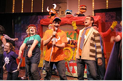
Everything the Story Pirates http://storypirates.org/ perform comes from the minds of kids. This clever team of actors and improv comedians will present eight to ten brief sketches based on material written by children from all around the country. Watch as they transform these original stories and ideas into wild, hilarious shows that include live music with hysterical songs featuring colorful sets and props. Sketches range from a night at the rodeo to show-and-tell with a kid’s favorite pet monster. Capping off the performance is a new story, improvised on the spot based on ideas from kids in the audience. The show appeals to families with children ages 5 through 11, though Jeremy Basescu, Associate Producing Director, notes “We often have three-year-olds at our show…and they flock to it.”
Founded in 2003 by ten Northwestern University graduates including actress and comedian Kristen Schaal, The Story Pirates is endorsed by Jon Stewart, who calls the group “crazy entertaining.” Conan O’Brien appeared in a Story Pirates show called “Charlie has a Special Wish,” written by a third grader from Los Angeles and said “This is the best writing I’ve worked with in a long time.” The Story Pirates reach kids all over the world through their free podcast, available on iTunes, and show on Sirius XM Radio.
“Story Pirates will put smiles on the faces of kids and parents, and show children how cool it is to see another child’s story come to life on stage.” says Randi Benesch, Gordon Center Managing Director. “Parents, this show will provide the perfect moment to hand your children notebooks to write their own stories!”
The Peggy and Yale Gordon Center for Performing Arts is Baltimore County’s premiere arts destination. The Gordon Center offers an eclectic variety of professional entertainment in music, theater, dance, family programming and film. You will experience world-class acoustics in an intimate, state-of-the-art venue. Free parking in well-lit spaces, handicap accessible, and equipped with a special RF system for the hearing impaired, the Gordon Center can be enjoyed by all.
Some cool precision machining in china images:
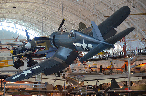
Steven F. Udvar-Hazy Center: Vought F4U-1D Corsair, with P-40 Warhawk in background

Image by Chris Devers
Quoting Smithsonian National Air and Space Museum | Vought F4U-1D Corsair :
By V-J Day, September 2, 1945, Corsair pilots had amassed an 11:1 kill ratio against enemy aircraft. The aircraft’s distinctive inverted gull-wing design allowed ground clearance for the huge, three-bladed Hamilton Standard Hydromatic propeller, which spanned more than 4 meters (13 feet). The Pratt and Whitney R-2800 radial engine and Hydromatic propeller was the largest and one of the most powerful engine-propeller combinations ever flown on a fighter aircraft.
Charles Lindbergh flew bombing missions in a Corsair with Marine Air Group 31 against Japanese strongholds in the Pacific in 1944. This airplane is painted in the colors and markings of the Corsair Sun Setter, a Marine close-support fighter assigned to the USS Essex in July 1944.
Transferred from the United States Navy.
Manufacturer:
Vought Aircraft Company
Date:
1940
Country of Origin:
United States of America
Dimensions:
Overall: 460 x 1020cm, 4037kg, 1250cm (15ft 1 1/8in. x 33ft 5 9/16in., 8900lb., 41ft 1/8in.)
Materials:
All metal with fabric-covered wings behind the main spar.
Physical Description:
R-2800 radial air-cooled engine with 1,850 horsepower, turned a three-blade Hamilton Standard Hydromatic propeller with solid aluminum blades spanning 13 feet 1 inch; wing bent gull-shaped on both sides of the fuselage.
• • • • •
Quoting Smithsonian National Air and Space Museum | Curtiss P-40E Warhawk (Kittyhawk IA):
Whether known as the Warhawk, Tomahawk, or Kittyhawk, the Curtiss P-40 proved to be a successful, versatile fighter during the first half of World War II. The shark-mouthed Tomahawks that Gen. Claire Chennault’s “Flying Tigers” flew in China against the Japanese remain among the most popular airplanes of the war. P-40E pilot Lt. Boyd D. Wagner became the first American ace of World War II when he shot down six Japanese aircraft in the Philippines in mid-December 1941.
Curtiss-Wright built this airplane as Model 87-A3 and delivered it to Canada as a Kittyhawk I in 1941. It served until 1946 in No. 111 Squadron, Royal Canadian Air Force. U.S. Air Force personnel at Andrews Air Force Base restored it in 1975 to represent an aircraft of the 75th Fighter Squadron, 23rd Fighter Group, 14th Air Force.
Donated by the Exchange Club in Memory of Kellis Forbes.
Manufacturer:
Curtiss Aircraft Company
Date:
1939
Country of Origin:
United States of America
Dimensions:
Overall: 330 x 970cm, 2686kg, 1140cm (10ft 9 15/16in. x 31ft 9 7/8in., 5921.6lb., 37ft 4 13/16in.)
Materials:
All-metal, semi-monocoque
Physical Description:
Single engine, single seat, fighter aircraft.
Steven F. Udvar-Hazy Center: Yellow Northrop N1M flying wing airplane, in front of Northrop P-61C Black Widow and tail of the Boeing B-29 Superfortress “Enola Gay”, et al
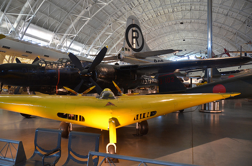
Image by Chris Devers
See more photos of this, and the Wikipedia article.
Details, quoting from Smithsonian National Air and Space Museum: Steven F. Udvar-Hazy | Northrop N1M:
John K. “Jack” Northrop’s dream of a flying wing became a reality on July 3, 1940, when his N-1M (Northrop Model 1 Mockup) first flew. One of the world’s preeminent aircraft designers and creator of the Lockheed Vega and Northrop Alpha, Northrop had experimented with flying wings for over a decade, believing they would have less drag and greater efficiency than conventional designs. His 1929 flying wing, while successful, had twin tail booms and a conventional tail. In the N-1M he created a true flying wing.
Built of plywood around a tubular steel frame, the N-1M was powered by two 65-horsepower Lycoming engines, later replaced with two 120-horsepower Franklins. While its flying characteristics were marginal, the N-1M led to other designs, including the Northrop XB-35 and YB-49 strategic bombers and ultimately the B-2 stealth bomber.
Transferred from the United States Air Force.
Manufacturer:
Northrop Aircraft Inc.
Date:
1940
Country of Origin:
United States of America
Dimensions:
Wingspan: 11.6 m (38 ft)
Length: 5.2 m (17 ft)
Height: 1.5 m (5 ft)
Weight, gross: 1,814 kg (4,000 lb)
Top speed: 322 km/h (200 mph)
Engine: 2 Franklin 6AC264F2, 120 hp
Overall: 72in. (182.9cm)
Other: 72 x 204 x 456in. (182.9 x 518.2 x 1158.2cm)
Materials:
Overall: Plywood
Physical Description:
Twin engine flying wing: Wood, painted yellow.
Long Description:
The N-1M (Northrop Model 1 Mockup) Flying Wing was a natural outgrowth of John K. “Jack” Northrop’s lifelong concern for an aerodynamically clean design in which all unnecessary drag caused by protruding engine nacelles, fuselage, and vertical and horizontal tail surfaces would be eliminated. Developed in 1939 and 1940, the N-1lM was the first pure all-wing airplane to be produced in the United States. Its design was the forerunner of the larger all-wing XB-35 and YB-49 bomber! reconnaissance prototypes that Northrop hoped would win Air Force production contracts and eventually change the shape of modern aircraft.
After serving apprenticeships with the Lockheed brothers and Donald Douglas in the early 1920s and designing the highly successful and innovative Lockheed Vega in 1927, Northrop in the late 192Os turned his attention to all-wing aircraft. In 1928, he left the employ of Lockheed and organized the Avion Corporation; a year later he produced his first flying wing, which incorporated such innovative features as all-metal, multicellular wing and stressed-skin construction. Although the 1929 flying wing was not a true all-wing design because it made use of external control surfaces and outrigger tail booms, it paved the way for the later N-1 M, which proved the basic soundness of Northrop’s idea for an all-wing aircraft. At the time, however, Northrop did not have the money to continue developing the all-wing idea.
In 1939, Northrop formed his own aircraft company, Northrop Aircraft, Inc., and as a result was in a position to finance research and development of the N-1M. For assistance in designing the aircraft, Northrop enlisted the not aerodynamicist Dr. Theodore von Karman, who was at the time Director of the Guggenheim Aeronautical Laboratory at the California Institute Technology, and von Karman’s assistant, Dr. William R. Sears. Walter J. Cerny, Northrop’s assistant design chief, became the overall supervisor for the project. To determine the flight characteristics of an all-wing design, Northrop Cerny conducted extensive wind tunnel tests or flying wing models. Ultimately, the design of the N-1 M benefited from the new low-drag, increase stability NACA airfoils as well as improved flaps spoilers, and other aerodynamic devices.
After a period of a year, the N-1M, nicknamed the “Jeep,” emerged in July 1940 as a boomerang-shaped flying scale mockup built 01 wood and tubular steel with a wingspan of 38 feet a length of 17 feet, and a height of 5 feet. Pitch and roll control was accomplished by means of elevons on the trailing edge of the wing, which served the function of both elevator and aileron the place of the conventional rudder was a split flap device on the wing tips; these were originally drooped downward for what was thought to be better directional stability but later straightened.
Controlled by rudder pedals, the split flaps, or “clamshells,” could be opened to increase the angle of glide or reduce airspeed and thus act as air brakes. The center of gravity, wing sweep, arrangement of control surfaces, and dihedral were adjustable on the ground. To decrease drag, the aircraft’s two 65-hp Lycoming 0-145 four-cylinder engines were buried within the fuselage. These were later discovered to be lacking in sufficient power to sustain lift and were replaced by two 120-hp six-cylinder 6AC264F2 air-cooled Franklin engines.
The N-1M made its first test flight on July 3, 1940, at Baker Dry Lake, California, with Vance Breese at the controls. Breese’s inaugural flight in the N-1 M was inauspicious. During a high-speed taxi run, the aircraft hit a rough spot in the dry lake bed, bounced into the air and accidentally became airborne for a few hundred yards. In the initial stages of flight testing, Breese reported that the aircraft could fly no higher than 5 feet off the ground and that flight could only be sustained by maintaining a precise angle of attack. Von Karman was called in and he solved the problem by making adjustments to the trailing edges of the elevons.
When Vance Breese left the N-1 M program to test-fly the North American B-25, Moye Stephens, the Northrop company secretary, took over testing of the aircraft. By November 1941, after having made some 28 flights, Stephens reported that when attempting to move the N-1M about its vertical axis, the aircraft had a tendency to oscillate in what is called a Dutch roll. That is, the aircraft’s wings alternately rose and fell tracing a circular path in a plane that lies between the horizontal and the vertical. Although Stephens was fearful that the oscillations might not be controllable, he found that adjustments to the aircraft’s configuration cleared up the problem. In May 1942, Stephens was replaced by John Myers, who served as test pilot on the project for approximately six months.
Although the exact period of flight testing for the N-1M is difficult to determine because both Northrop and Army Air Forces records have been lost, we do know that after its initial test flight at Baker Dry Lake, the aircraft was flown at Muroc and Rosamond Dry Lake, and at Hawthorne, California, and that late in the testing program (probably after January 1943) it was towed by a C-47 from Muroc to Hawthorne on its last flight with Myers as the pilot.
From its inception, the N-1M was plagued by poor performance because it was both overweight and chronically underpowered. Despite these problems, Northrop convinced General H. H. Hap” Arnold that the N-1 M was successful enough to serve as the forerunner of more advanced flying wing concepts, and the aircraft did form the basis for Northrop’s subsequent development of the N-M9 and of the larger and longer-ranged XB-35 and YB-49 flying wings.
In 1945, Northrop turned the N-1M over to the Army Air Forces in the hope that it would someday be placed on exhibit. On July 12, 1946, the aircraft was delivered to Freeman Field, Indiana. A little over a month later, the N-1M was given to the National Air Museum and placed in storage at Park Ridge, Illinois. On May 1,1949, the aircraft was placed in the Museum’s collection, and a few years later moved in packing crates to the Museum’s Preservation, Restoration and Storage Facility in Suitland, Maryland. In 1979, the restoration of the N-1M began, and by early 1983, some four decades after it had made its final flight, the aircraft had been returned to its original condition.
• • • • •
Quoting Smithsonian National Air and Space Museum | Northrop P-61C Black Widow:
The P-61 Black Widow was the first U.S. aircraft designed to locate and destroy enemy aircraft at night and in bad weather, a feat made possible by the use of on-board radar. The prototype first flew in 1942. P-61 combat operations began just after D-Day, June 6, 1944, when Black Widows flew deep into German airspace, bombing and strafing trains and road traffic. Operations in the Pacific began at about the same time. By the end of World War II, Black Widows had seen combat in every theater and had destroyed 127 enemy aircraft and 18 German V-1 buzz bombs.
The Museum’s Black Widow, a P-61C-1-NO, was delivered to the Army Air Forces in July 1945. It participated in cold-weather tests, high-altitude drop tests, and in the National Thunderstorm Project, for which the top turret was removed to make room for thunderstorm monitoring equipment.
Transferred from the United States Air Force.
Manufacturer:
Northrop Aircraft Inc.
Date:
1943
Country of Origin:
United States of America
Dimensions:
Overall: 450 x 1500cm, 10637kg, 2000cm (14ft 9 3/16in. x 49ft 2 9/16in., 23450.3lb., 65ft 7 3/8in.)
• • • • •
Quoting Smithsonian National Air and Space Museum | Boeing B-29 Superfortress “Enola Gay”:
Boeing’s B-29 Superfortress was the most sophisticated propeller-driven bomber of World War II and the first bomber to house its crew in pressurized compartments. Although designed to fight in the European theater, the B-29 found its niche on the other side of the globe. In the Pacific, B-29s delivered a variety of aerial weapons: conventional bombs, incendiary bombs, mines, and two nuclear weapons.
On August 6, 1945, this Martin-built B-29-45-MO dropped the first atomic weapon used in combat on Hiroshima, Japan. Three days later, Bockscar (on display at the U.S. Air Force Museum near Dayton, Ohio) dropped a second atomic bomb on Nagasaki, Japan. Enola Gay flew as the advance weather reconnaissance aircraft that day. A third B-29, The Great Artiste, flew as an observation aircraft on both missions.
Transferred from the United States Air Force.
Manufacturer:
Boeing Aircraft Co.
Martin Co., Omaha, Nebr.
Date:
1945
Country of Origin:
United States of America
Dimensions:
Overall: 900 x 3020cm, 32580kg, 4300cm (29ft 6 5/16in. x 99ft 1in., 71825.9lb., 141ft 15/16in.)
Materials:
Polished overall aluminum finish
Physical Description:
Four-engine heavy bomber with semi-monoqoque fuselage and high-aspect ratio wings. Polished aluminum finish overall, standard late-World War II Army Air Forces insignia on wings and aft fuselage and serial number on vertical fin; 509th Composite Group markings painted in black; “Enola Gay” in black, block letters on lower left nose.