Image from web page 342 of “Railway master mechanic [microform]” (1895)

Image from web page 342 of “Railway master mechanic [microform]” (1895)

Check out these mechanical engineering china images:

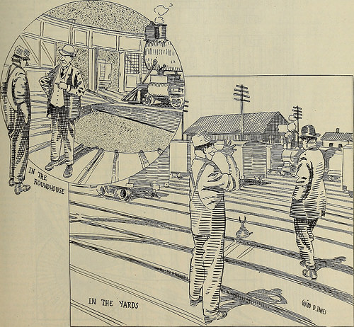
Image from page 342 of “Railway master mechanic [microform]” (1895)
mechanical engineering china
Image by World wide web Archive Book Images
Identifier: railwaymastermec33newy
Title: Railway master mechanic [microform]
Year: 1895 (1890s)
Authors:
Subjects: Railroads Railroads
Publisher: New York : [Simmons-Boardman Pub. Corp.]
Contributing Library: MIT Libraries
Digitizing Sponsor: Boston Library Consortium Member Libraries

View Book Web page: Book Viewer
About This Book: Catalog Entry
View All Pictures: All Pictures From Book

Click here to view book online to see this illustration in context in a browseable on-line version of this book.

Text Appearing Ahead of Image:
s of railway function projected in Turkey.The Chinese market place ought to also be open, despite the fact that diplomaticpressure in this direction may possibly be necessary to secure the ob-servance of open competitors provided for by specific treaties.But apart from China, different opportunities for in search of freshbusiness in various components are held in prospect for the close to fu-ture.—Mechanical Engineer. Machinists hammers could be effectively hardened on thestriking face by heating the head to a cherry red and dippingthe face to be hardened into a water tank in which is a pipeleading up from the bottom with the opening a short distancebelow the water surface. The other end of the pipe is connectedto the city water mains or other supply from which some headmay be obtained. By turning on the water so that it flowsthrough the pipe with enough force to agitate the surface andholding the hot hammer head with the face just beneath the sur-face of the water, the face will be hardened and the rest of thehead remain soft. o

Text Appearing Soon after Image:
Not an Unusual Scenario. The Mechanics Jurisdiction Need to be Extended. v.)o RAILWAY MASTER MECHANIC August, 1909.

Note About Photos
Please note that these pictures are extracted from scanned web page images that might have been digitally enhanced for readability – coloration and look of these illustrations could not perfectly resemble the original function.

131105-N-TG831-030.jpg
mechanical engineering china
Image by Commander, U.S. 7th Fleet
SOUTH CHINA SEA (Nov. 5, 2013) Gas Turbine Systems Technician (Mechanical) 3rd Class David Muncey, assigned to the Ticonderoga-class guided-missile cruiser USS Antietam (CG 54), logs information from an engineering console in the ship’s main engineering handle center. Antietam is on patrol with the George Washington Carrier Strike Group in the U.S. 7th Fleet location of responsibility supporting security and stability in the Indo-Asia-Pacific region. (U.S. Navy photo by Mass Communication Specialist 3rd Class Declan Barnes)

131105-N-TG831-030
mechanical engineering china
Image by SurfaceWarriors
131105-N-TG831-030 SOUTH CHINA SEA (Nov. five, 2013) Gas Turbine Systems Technician (Mechanical) 3rd Class David Muncey, assigned to the Ticonderoga-class guided-missile cruiser USS Antietam (CG 54), logs information from an engineering console in the ship’s principal engineering manage center. Antietam is on patrol with the George Washington Carrier Strike Group in the U.S. 7th Fleet location of responsibility supporting safety and stability in the Indo-Asia-Pacific region. (U.S. Navy photo by Mass Communication Specialist 3rd Class Declan Barnes/Released)

Cleared for release by CTF70 PAO Lt. Cmdr. Paul Macapagal, paul.macapagal@ctf70.navy.mil

Speedy prototyping and filling commercial pipeline

Approaches and apparatus supply a means to swiftly develop and modify speedy prototype surface coverings for customer review and approval, and fill the commercial pipeline even though a lot more standard production gear is obtained, installed and tested. The present apparatus to speedy prototype and fill the commercial pipeline includes a digital printing method to print a film and a press for laminating and embossing the printed film to a substrate. The press makes use of an embossing plate or roll, which is produced from ebonite or by three-dimensional printing gear. These plates and rolls can be produced within two or three days or much less.

A technique of speedy prototyping and manufacture of surface coverings obtaining a substrate, a print layer and a put on layer, the strategy comprising: a. producing aprototype surface covering making use of a digital printing program to print the print layer and a press to emboss the wear layer, wherein the press comprises an embossing tool chosen from the group consisting of an embossing plate and an embossing roll, theembossing tool produced by 3-dimensional printing, and b. utilizing the digital printing system and press to fill the commercial solution pipeline.

Developing new styles for surface coverings, by producing a prototype to show a possible consumer prior to making a mass produced product available, is high-priced and usually requires three months or more. This is mainly due to the price and timeto create print cylinders and embossing cylinders.

Consumers are demanding shorter and shorter improvement instances and far more input into the final style of the item. It would be advantageous to have a signifies to swiftly (within a matter of days) modify a design and style, produce a prototype that willfaithfully imitate the final item, and be capable of producing industrial quantities of the final item at a rate to meet initial commercial demand.

Existing approaches of prototyping surface covering are costly, due to the fact each and every change in design and style requires the rotogravure printing cylinder and the common embossing roll to be re-etched or re-engraved. If the surface covering is chemicallyembossed, any modify in the chemical embossing also demands re-etching or re-engraving of the print cylinder. The approach of remaking the cylinders is costly and time consuming.

The present invention overcomes this disadvantage by using digital printing to make speedy adjustments in the print pattern and chemical embossing pattern. The chemical embossing pattern is developed by printing a blowing agent modifier, such as ablowing inhibitor or a blowing accelerator.

The present invention also uses mechanical embossing tools that can be made within two or 3 days. The embossed plates used in a stacker press are less expensive and faster to make than the conventional mechanical embossing rolls utilised in thetypical manufacture of tile and sheet goods. Ebonite embossing cylinders and embossing plates, and cylinders and plates made by three-dimensional printing gear can also be created inside two or three days. For that reason, the fast prototyping of thesurface covering necessary by the present invention is achieved.

Additional, time to industry is drastically shortened by using the digital printing system, stacker press, ebonite mechanical embossing cylinders and plates, or mechanical embossing cylinders and plates made by three-dimensional printing equipmentto fill the commercial item pipeline. Whilst the pipeline is becoming filled, the classic rotogravure printing cylinders and mechanical embossing rolls can be created, and the less costly to manufacture production line, which includes the rotogravureprinting cylinders and mechanical embossing rolls, can be set up. After the rotogravure printing and mechanical embossing line is up and running, the digital printing method and stacker press, ebonite embossing rolls or three-dimensional printing rollsmay be utilized to create an additional new tile or sheet goods.

In a preferred embodiment, the prototypes and industrial solution which fills the industrial pipeline makes use of a digital printing system and an embossing technique in which the embossing tool can be produced inside two or 3 days. The digital printingsystem permits fast and versatile altering of the prototype style.

Although the prototyping embossing systems that are envisioned create tile at a slower rate than standard tile manufacturing lines and do not use an embossing tool having a extended commercial production lifespan, the tools can be created within two orthree days and are durable enough to make sufficient industrial solution to fill the commercial pipeline and permit time to manufacture and set up the standard commercial embossing tools.

1 goal of this invention is to enable the user to speedy prototype and/or manufacture vinyl tiles T, either the regular residential sort D.I.Y. vinyl tiles or luxury vinyl tiles sheet goods S, which includes residential and commercialresilient flooring and other surface coverings, specifically those that are printed and mechanically embossed. At present, the manufacturing procedure utilized to develop and make vinyl tile and sheet goods can take as lengthy as 90 days. The presentinvention will significantly reduce the cycle-time to make such vinyl tiles and sheet goods to as brief as a single week or significantly less, thereby providing the user a considerable marketplace benefit.

We are The Leading 1 rapid prototype store,we sell speedy prototypes,you can purchase Safe Plastic mold from us.

Status And Export Plastic Machinery Industry Analysis – China Sheet Metal Cabinet

Status And Export Plastic Machinery Industry Analysis – China Sheet Metal Cabinet

China’s plastics machinery manufacturing industry 50 years from the 20th century produced the very first product considering that, right after nearly half a century, specially the rapid development because the reform and opening up, and now have constructed a complete variety, the principal technical and economic indices, or reached the international advanced level, supporting internationalized production gradually specialized, full with large-scale industrial technique, the product basically meet the domestic demand, speedy increase in export capacity. I. Current Situation of China plastic machinery manufacturing sector currently engaged in manufacturing plastics machinery and connected enterprises, about 600 units, of which plastic molding equipment can offer about 250. China’s plastics machinery market has a considerable scale, at present, China’s leading plastic machinery production capacity far more than 10 million sets, which, out of a lot more than 8,000 sets of equipment, 30,000 sets of injection molding machines, blow molding equipment, a lot more than three,000 sets of plastic machinery annual turnover of 8. billion ~ 10 billion yuan. Plastic goods from the industry evaluation, combined with our existing plastic machinery production capacity into full play, from 2001 to 2010, China’s domestic market place capacity of plastic machinery items the typical annual development of about six%. 2000, 2005 had been 80 billion yuan, 11 billion yuan, is expected to reach 14.five billion by 2010. With the improvement in the quality of our items and variety enhance, plastic machinery items in the domestic industry share will enhance as anticipated were 70%, 75% and 80% plastic machinery items have been 5.6 billion total industrial output worth , 8.25 billion yuan and 11.six billion yuan. With the improve of China’s exports in 2010, China’s industrial output worth of plastic machinery goods reached 140 billion yuan, 2.33 instances in 2000, the annual typical growth rate of about 9% in 2001 and 2005 annual growth rate of 10% 2006 to 2010 annual development rate of 8%. Plastic machinery goods from the quantitative evaluation, 2000, 2005, were 5.five million, 7.5 million units in 2010 to ten million units, of which about 35% of the injection molding machine, extruder, 25%, about Blow Molding Machine five%, 35% of other presses. Second, China’s exports of plastic machinery manufacturing business of plastic equipment for basic use in addition to meet the domestic demand, gear exports also increased year by year. three years, China’s plastics machinery exports in the period of quickest development in history. Lengthy, exports have been about 50 million U.S. dollars in 1998, more than 100 million U.S. dollars in 2001 to 238 million U.S. dollars, up 31.09 percent more than 2000. Experts believe that the future of China’s exports of plastic machinery injection molding machine will be based. From the quantitative analysis of the export is expected to share all kinds of aircraft were: 60.4% of injection molding machines, extruders 6.eight%, 11.7% blow molding machine, the other presses 21.1%. From the quantity of plastic machinery products export point of view, 74.1% of injection molding machines, extruders, eight.1%, blow molding machine, 8%, other plastic machinery merchandise accounted for 9.eight%. In 2002, total exports of plastic machinery market than in 2001. Powerful export momentum in 2002 the enterprises of Ningbo Haitian Co., Ltd. and Zhejiang Shengda Plastic Machinery Co., Ltd., respectively, compared with an enhance of three.six% in 2001 and three.39%. 3, mold export Additionally, the rise of China Mould exports momentum. In 2002, China exported 19,500 tons mold, to 252 million U.S. dollars. Among them, the plastic or rubber mold to 467,800 units, about 172 million U.S. dollars, accounting for 68.3% of total exports of the mold. Major sources of exports of plastic molds to Guangdong, Zhejiang, Shanghai and Fujian, were abrasive exports accounted for 57%, 13.9%, 11% and 5.2%. The principal export markets are Hong Kong, China, Japan, China Taiwan Province, United States and Singapore, followed by Vietnam, Thailand, Malaysia, South Korea, India, Indonesia and Mexico. Despite the fact that the origin of China’s plastic mold all over the country but mainly concentrated in the southeast coastal provinces and cities, especially in the Pearl River Delta and Yangtze River Delta location exactly where the concentration. By provinces, the Guangdong Province and Zhejiang Province, the most created. The two provinces generate plastic mold mold production accounts for about two / three. , Dongguan, Shenzhen, Shunde, Guangdong Province, the most advanced plastic mold parts and Ningbo, Taizhou, Zhejiang Province, is the most sophisticated producer. Plastic injection mold plastic mold of the key products, mostly serves the automotive, motorcycle and electrical industries.

I am an professional from cnc-machiningparts.com, while we supplies the good quality solution, such as China Sheet Metal cabinet , Hydraulic Couplings, machining components supplier,and a lot more.

Uncover Much more China Sheet Metal Articles

Guidelines For Speedy Prototype Iterative Development Life Cycle

Guidelines For Speedy Prototype Iterative Development Life Cycle

The rapid prototype iterative prototyping method, on the other hand, will facilitate functionally scoped, yet entirely deployable versions of the software program to be delivered to customers incrementally. Functionality is enhanced by means of new iterations until the final version is reduce out. Thus, the technique will be created as executable computer software elements in an evolving manner, every single iteration increasing in functionality and ultimately encompassing the requirements of the complete production technique.

Each and every iteration consists of one particular or a lot more of the following development cycle method actions:
Specifications capture
Evaluation
Design and style
Implementation
Testing

Modify is anticipated all through all stages of the development. Technical dangers are assessed and prioritised early in the life-cycle and are revised for every iteration. The dangers linked with each iteration are alleviated with the profitable completion of the iteration.

Iterative prototyping will make certain fast prototype development, measurable progress and the ideal acceptability among customers.

Stage I – Starting a Project and Analysing Needs

Defining requirements for software development is the responsibility of the buyer. Buyer provides the dilemma statement along with the business requirement specification. Sometimes, the enterprise needs specification is generated by way of numerous interactions with the client.

The project team would determine the functional phases in which the system will be created and delivered. Functions inside each and every phase would comply with an iterative development approach.

As a part of analysing specifications, the project group could undertake visual modelling of the needs along with the logical grouping of scenarios and recommended possibilities for implementation.

This would generally consist of:

Use Case diagram(s) for the proposed technique.
Preliminary Class Diagram showing suggested new classes and other currently current classes.

Evaluation of requirement scenarios and any other info needed to give an overview of the business process.

Stage II – The First Iteration

Scenarios of evaluation are the primary inputs to this stage.

The primary objective of the first iteration would be to concentrate on the class diagram and establish the data components. This is aimed at addressing the database danger.

Activities of this stage consist of:
Creating the data model
Deploying the database
Identifying the application and operations on classes. This will decide logical units of code that would be enhanced and re-used more than iterations.
Identification of a user interface that can address presentation concerns in relation to functionality.
Prototyping the design
Preliminary user documentation (operational instructions)

Either of the following two strategies can be agreed upon for prototyping:

Create a single prototype that aims at crystallizing the base functional components without finer specifics of presentation.

Create several prototype options with the identical base functionality coverage for diverse presentation styles. This might give users a better feel of the final technique. Also, presentation concerns in relation to functionality usually get identified earlier rather than in the course of the final stages of iteration.

The strategy to be followed will be determined by feedback from the client and the criticality of the presentation interface in relation to the organization approach as suggested by the requirement scenarios of Stage I.

Stage III – Organizing the Iteration Procedure

User feedback from the initial iteration will enable the project group to strategy subsequent iterations.

Iterations would be planned based on the following problems:
Highest dangers are tackled first. This necessarily guarantees convergence towards preferred functionality as the project progresses by way of the iterations and also guarantees significantly less threat coupled with minimum investment.

Figuring out the anticipated quantity of iterations prior to the application can be shifted out of the iterative stage into final development. These are the intermediate iterations. The quantity of intermediate iterations would be determined by grouping scenarios (as defined in Stage I) to collectively provide a meaningful chunk of method functionality. For most projects, about five (plus or minus two) such intermediate iterations suffice.

The iteration rolling into final improvement may possibly or may possibly not match presentation GUI wants of users. This will rely on the method utilized in Stage II.

The final improvement would be conducted as penultimate iterations(s). The focus of these iterations would be to incorporate finer details into the software, viz. presentation, error messages, print options, multi-lingual assistance and so on. The maximum number of such penultimate iterations have to also be planned and defined – typically, two rounds would suffice.

When the functionality has been crystallized, test preparing can be initiated.

Concentrate of Iterations

Focus of iterations would change as functional depth is added to every iteration.

The data model and application style should necessarily be validated and finalized in iteration II. As a result, class diagrams are finalized early in the iterative development cycle. At this time, it would also be attainable to define the operations on classes.

Subsequent iterations would concentrate on the business rules (occasion handling, procedural logic). That is, implementing approach bodies.

Presentation GUI would be regarded as soon as the functionality (such as business rules) has been authorized. This also offers the go-ahead for test arranging.

Every iteration would be released with minimal testing. Testing focus will be put into the penultimate iteration(s) that is, in the final improvement stage.

Feedback is crucial to an iterative process without having such feedback, there are no further iterations.

Team Profile

The focus of iterations determines the composition of the group.

The initial two iterations are the principal responsibility of analyst/designers. Worthwhile contribution from programmers in this stage is not anticipated.

Subsequent iterations are carried out successfully by programmers with minimal interference by analyst/designers.

Test preparing is the principal duty of the enterprise analysts.

Presentation GUI and system testing stages in the penultimate iterations are also best accomplished by company analysts.

Because there is a clear distinction in between analysts and programmers, it would be possible to define involvement levels of individuals for every iteration primarily based on the focus of the iteration. This would allow the team to take up new functional phases in parallel, well ahead of a final delivery. That is, analyst/designers could move onto a new functional phase although the programmers see the existing functions by way of final iterations.

Stage III – Penultimate Iteration(s)

This marks the finish of the user feedback stage. The functionality along with business guidelines and presentation is now finalized. Focus alterations to finer information, presentation GUI and technique testing.

Other activities consist of:
Program Documentation
Finalization of class, sequence, state-transition and element diagrams
User Documentation
Depth to the operational instructions as determined by the document format standardized
Good quality Assurance
Code walkthrough, QA testing and correction

Stage IV – Computer software Packaging and Delivery

The software will be packaged, appropriately versioned and delivered. The “readme” file will list salient attributes of the functionality, any unique areas of consideration and installation directions. All user and technique documentation will be part of the release.

Longxiang Industrial Restricted is providing specialist precise fast manufacturing, prototype rapid, 3d prototype, plastic prototype, 3d prototyping, 3d speedy prototyping, plastic prototyping, fast prototype and fast tooling in China. We appear forward to participating at the achievement of your next project.

Uncover Far more Speedy Prototype China Articles
Butterball – China Hydraulic Couplings – Metal Fabrication Manufacturer

Butterball – China Hydraulic Couplings – Metal Fabrication Manufacturer

History
The name Butterball was initially registered as trademark #378,438 on June 11, 1940 by Ada Walker of Wyoming, Ohio. Leo Peters purchased the trademark in February 1951. Leo Peters licensed the name to Swift and Co. for 10 years prior to selling it in the 60’s. Peters sold the name “Butterball” to Swift and Co. which was later acquired by ConAgra, but retained rights to the use of the name for his butter products and the firm he founded which is still in operation today, known as Butterball Farms, Inc.
In October 2006, ConAgra’s Butterball branded turkey organization was sold to North Carolina primarily based Carolina Turkeys, which renamed itself Butterball LLC.
Turkey Talk-Line
Beginning in late 1981, Butterball has maintained a toll-free of charge telephone line known as the Turkey Speak-Line to assist buyers with numerous cooking difficulties and questions. Eleven thousand individuals known as in 1981, and in recent years the quantity has grown to more than 200,000 each and every vacation season. Every of the operators holds a degree in either dietetics or residence economics, roughly half of which are Masters-level. The most frequent question asked is how lengthy a turkey requires to defrost.
In The West Wing episode “The Indians in the Lobby”, President Josiah Bartlet calls the number (referred to as the “Butterball Hotline” in the script) to discuss stuffing and cooking his Thanksgiving turkey.
Controversies
An undercover PETA video investigation released in July 2006 showed Butterball personnel beating and inhumanely killing turkeys.
References
^ Smithfield Foods::Investor Details::Press Releases
^ Turkey Merchandise|Butterball
^ Butterball Farms solution web page
^ USA These days: Sale of Butterball turkey enterprise not expected to modify Thanksgiving icon
^ Butterball’s Residence of Horrors
Notes
Taylor, Rod – “Backward Glance: Speaking Turkey”, PROMO Magazine, November 2004
External hyperlinks
Butterball, LLC – Turkey Purveyor
Butterball Farms, Inc. – Butter Purveyor
This meals and/or confectionery corporation or organization-connected write-up is a stub. You can support Wikipedia by expanding it.
v d e
This brand-name food or drink solution-associated report is a stub. You can assist Wikipedia by expanding it.
v d e
Categories: Brand name poultry | Meleagrididae | Butter | Food organization stubs | Brand name meals products stubsHidden categories: All articles with unsourced statements | Articles with unsourced statements from February 2010

The e-commerce firm in China offers high quality products such as China Hydraulic Couplings , Metal Fabrication Manufacturer, and more. For far more , please visit

Far more China Metal Fabrication Articles

Hydraulic Mechanical Gearbox

Hydraulic Mechanical Gearbox

The invention relates, on the 1 hand, to a hydro mechanical gearbox with a hydraulic pump, a hydraulic motor and a set of planetary gears, whereby the pressure line of the hydraulic pump is performed back, through the inserted hydraulic motor, to the suction line of the hydraulic pump, thereby forming a circuit, and whereby either the sun wheel or the planet-carrier of the set of planetary gears is coupled in a rotationally fixed manner to the driven shaft of the gearbox, and the other one of these two components of the planetary gear is coupled in the exact same manner to the output shaft of the gearbox.

A series of gearbox styles, which also contain the hydraulic gearbox in which a hydraulic pump drives a hydraulic motor through an oil circuit, have turn out to be recognized from the prior art. In hydraulic gearboxes of this sort, nevertheless, the efficiency declines swiftly with rising rotational speeds, considering that flow resistances make themselves felt in a disadvantageous manner as the speed of flow of the hydraulic oil increases. Consequently, a especially big quantity of power is wasted precisely when the maximum output is needed of the gearbox, with the outcome that the internal-combustion motor providing the drive has to be overdimensioned to a relatively main extent.

These disadvantages of the arrangements known from the prior art outcome in the difficulty, which is initiating the present invention, of designing an infinitely variable gearbox which develops its optimum efficiency precisely when the maximum throughput of power occurs.

This difficulty is effectively solved in a gearbox of the above described type when one rotational unit of the hydraulic motor, preferably its rotor, is coupled in a rotationally fixed manner to the driven shaft of the gearbox, and the other unit of the hydraulic motor, preferably its static portion, is coupled either to the frame/housing of the gearbox or to its output shaft. As will be further explained later on, in an arrangement of this type, the delivery quantity of the hydraulic pump declines as the rotational speed of the output shaft rises, until it finally becomes absolutely zero at a maximum rotational speed.

This implies that, at high rotational speeds at which the greatest output is taken off at the output shaft, no flow losses happen in the hydraulics and therefore the efficiency reaches its maximum. Simply because of its favorable efficiency, a gearbox of this variety permits a reduction in the structural size of the driving motor. As 1 rotational part of the hydraulic motor is coupled in a rotationally fixed manner to the driven shaft of the gearbox, it is attainable to transfer rotational power from the output shaft of the gearbox by means of the hydraulic oil circuit to the driven shaft, so that in the case of a pushing load the stabilizing traits of a combustion engine can be used to limit the rotational speed of the gearbox components.

The inventive hydro mechanical gearbox offers the possibility of controlling the speed of a car via the gear ratio, even though the combustion engine runs at a practically continuous speed, exactly where the torque is as high as attainable or its efficiency has its very best value. The dynamical qualities of the inventive gearbox are superior, due to the fact at a standstill of the car the hydraulic pump runs at a higher speed, so that a wonderful quantity of rotational power is stored within its rotating masses. When the car begins, these rotating masses are decelerated, whereby the stored quantity of power is delivered at the output shaft in addition to the amount of power, which is straight transmitted from the combustion engine. So at the moment, when the car begins, the inventive hydro mechanical gearbox may have an efficiency of much more than 100%. This aspect is quite essential for tractors for agricultural purposes, which operate usually at a rough or steep landscape. If the tractor has to commence from an inclined position, at the moment of disconnecting the brake the gearbox has to deliver the full output at its output shaft.

A single feasible way of adjusting the gearing ratio of the gearbox according to the invention consists in the reality that the delivery quantity of the hydraulic pump is adjustable. With the intake volume of the hydraulic motor unchanged, it is attainable, by adjusting the delivery quantity of the hydraulic pump, to adjust the braking action of the latter and in this way accomplish an adjustment of the gearing of the gearbox. Axial piston pumps, for instance, are appropriate for this objective given that, in the case of these pumps, the inclination of the oblique disc actuating the axial piston is adjustable during operation. Axial manage pistons, which are connected to the pump casing in a rotationally fixed manner, are utilised for this purpose.

A hydraulic motor delivers a greater or lesser operating resistance, based upon the mechanical load, to the hydraulic oil taken in, and can for that reason be used for throttling the flow of oil. A single distinct benefit of such an arrangement lies in the truth that the energy drawn off as a result of the throttling-down of the hydraulic pump delivering the drive is not lost but is re-introduced to the driving shaft of the gearbox in the kind of an extra torque, so that the combustion engine is unburdened. Considering that it is also achievable, by varying the throttling, to influence the braking action of the hydraulic pump and, with it, the gearing ratio of the gearbox according to the invention, the mentioned invention offers for the possibility of adjusting the intake volume of the hydraulic motor.

If, as a result, the intake volume of the hydraulic motor is set reduced than the delivery volume of the hydraulic pump, the delivery flow of the latter is supported on the hydraulic motor, so that the hydraulic pump is braked. The use of an axial piston motor as the hydraulic motor suggests itself given that, in the case of the said hydraulic piston motor, adjustment of the intake volume is feasible by altering the inclination of the oblique disc actuated by the axial handle piston. A hydraulic motor of this sort is primarily based on a reversal of the operation of the hydraulic pump principle, so that the hydraulic motor can be constructed, at least in principle, so as to be structurally identical to the hydraulic pump coupled to the set of planetary gears.

It lies within the scope of the invention that the handle pistons for the hydraulic pump, and also, optionally, for the hydraulic motor, are hydraulically actuated. In this occasion, the hydraulic pressure required for this goal can be taken off, in a particularly advantageous manner, from a gas pressure/spring reservoir which is fed by the hydraulic pumps of the gearbox according to the invention.

Zhongyi Hydraulic Motor Business is a professional engaged in gearbox,radial piston motor,axial piston motor,piston motor,slewing transmission,danfoss motor,hydraulic orbital motor,hydraulic steering,hydraulic steering unit,hydraulic winch. All goods are strictly tested ahead of delivery by testing bench and complete testing facilities to ensure the quality.

Newest Sheet Metal Components China News

Newest Sheet Metal Components China News

Image from page 64 of “Sunset” (1898)
sheet metal parts china
Image by Net Archive Book Images
Identifier: sunset74jansout
Title: Sunset
Year: 1898 (1890s)
Authors: Southern Pacific Business. Passenger Department
Subjects:
Publisher: [San Francisco, Calif. : Passenger Dept., Southern Pacific Co.] Menlo Park, CA : Sunset Publishing Corporation
Contributing Library: World wide web Archive
Digitizing Sponsor: World wide web Archive

View Book Page: Book Viewer
About This Book: Catalog Entry
View All Pictures: All Images From Book

Click right here to view book on-line to see this illustration in context in a browseable on the internet version of this book.

Text Appearing Prior to Image:
arently changing it, andat the exact same time adding to the seem-ance of the fireplace unit? To discover outhow a lot smaller sized the opening shouldbe, experiment by making use of a big sheet ofcardboard to cover portion of the mouth,till you find the proportion that ef-fectively stops the smoking. (If indoubt as to proportions, send to Wash-ington, D. C, for Farmers BulletinNo. 1230.) An economical and sensible methodis to construct a grate and fender as illus-trated here. The minimum height ofthe grate and fender is 14 inches, and,as the height of the opening in the aver-age fireplace is among 30 and 34inches, this really cuts the openingdown to about a third its original size.Any machine-shop worker can makesuch a grate. The fender is most attrac-tive, produced out of hammered copper andwrought iron if no a single is found whodoes this operate, have a mechanic makeone out of sheet metal. The fender isneeded not only for appears, but in orderto reduce the draft beneath the fire.Becoming loose, it can be simply removed

Text Appearing After Image:
even though 1 cleans out the ashes andsweeps the hearth. The front of the grate is made of% by li/j-inch soft steel. The bottombars of the grate are reduce from I/2 by114-inch bars, and are spaced % inchapart, resting at front and rear on 2 by2-inch angle iron. If the grate is 20inches or more than in depth, it is far better tohave the center supported by anotherangle iron. The center grate bars areleft loose, so that they can be turnedover or replaced in case of warping. Inmost fireplaces the back is narrowerthan the front, in which case the trian-gular sides of the bottom of the grate(see sketch) can normally be made outof a piece of y^ by 6-inch sheet ironcut at an angle. It will be identified veryconvenient to have the grate resting ontwo or a lot more U-shaped legs for slidingit into the fireplace opening, although itcan be supported on bricks. Rivets(five/16-inch size) are utilised and %-inchholes are drilled which should take careof any inaccuracies in lining up theholes. The grate must be set in threeinches fro

Note About Pictures
Please note that these pictures are extracted from scanned page photos that may have been digitally enhanced for readability – coloration and look of these illustrations may possibly not completely resemble the original function.

Boeing B-17 & P-51 Mustangs – Duxford Airshow Oct 2010

Boeing B-17 & P-51 Mustangs – Duxford Airshow Oct 2010

Check out these precision engineering photos:

Boeing B-17 & P-51 Mustangs – Duxford Airshow Oct 2010
precision engineering
Image by Feggy Art
Boeing B-17 + P51 Mustangs at Duxford Airshow October 2010.

The Boeing B-17 Flying Fortress was a four-engine heavy bomber aircraft created in the 1930s for the United States Army Air Corps (USAAC). Competing against Douglas and Martin for a contract to develop 200 bombers, the Boeing entry outperformed each competitors and far more than met the Air Corps’ expectations. Despite the fact that Boeing lost the contract because the prototype crashed, the Air Corps was so impressed with Boeing’s style that they ordered 13 much more B-17s for additional evaluation. From its introduction in 1938, the B-17 Flying Fortress evolved through several style advances.

The B-17 was mainly employed by the United States Army Air Forces (USAAF) in the daylight precision strategic bombing campaign of World War II against German industrial and military targets. The United States Eighth Air Force primarily based at Thorpe Abbotts airfield in England and the Fifteenth Air Force based in Italy complemented the RAF Bomber Command’s nighttime area bombing in Operation Pointblank to support safe air superiority more than the cities, factories and battlefields of Western Europe in preparation for Operation Overlord. The B-17 also participated to a lesser extent in the War in the Pacific where it performed raids against Japanese shipping and airfields.

From its pre-war inception, the USAAC (later USAAF) touted the aircraft as a strategic weapon it was a potent, higher-flying, long-range bomber that was capable to defend itself, and to return residence despite extensive battle harm. It rapidly took on mythic proportions, and extensively circulated stories and photos of B-17s surviving battle damage enhanced its iconic status. With a service ceiling higher than any of its Allied contemporaries, the B-17 established itself as an effective weapons program, dropping more bombs than any other U.S. aircraft in Planet War II. Of the 1.five million metric tons of bombs dropped on Germany by U.S. aircraft, 640,000 tons were dropped from B-17s.

Registrations:

•B17: Memphis Belle, 124485, 44-83546, N3703G, 23060/LN-T
•Mustang 1: Miss Velma, N251RJ, NX251RJ, 44-84847
•Mustang 2: Ferocious Frankie, 413704, G-BTCD
•Mustang three: Large Beautiful Doll, G-HAEC

General qualities

•Crew: ten: Pilot, co-pilot, navigator, bombardier/nose gunner, flight engineer-best turret gunner, radio operator, waist gunners (2), ball turret gunner, tail gunner
•Length: 74 ft 4 in (22.66 m)
•Wingspan: 103 ft 9 in (31.62 m)
•Height: 19 ft 1 in (five.82 m)
•Wing region: 1,420 sq ft (131.92 m2)
•Airfoil: NACA 0018 / NACA 0010
•Aspect ratio: 7.57
•Empty weight: 36,135 lb (16,391 kg)
•Loaded weight: 54,000 lb (24,500 kg)
•Max takeoff weight: 65,500 lb (29,700 kg)
•Powerplant: 4× Wright R-1820-97 Cyclone turbo supercharged radial engines, 1,200 hp (895 kW) every

Overall performance

•Maximum speed: 287 mph (249 kn, 462 km/h)
•Cruise speed: 182 mph (158 kn, 293 km/h)
•Range: 2,000 mi (1,738 nmi, three,219 km) with 2,700 kg (6,000 lb) bombload
•Service ceiling: 35,600 ft (ten,850 m)
•Rate of climb: 900 ft/min (4.6 m/s)
•Wing loading: 38. lb/sq ft (185.7 kg/m2)
•Power/mass: .089 hp/lb (150 W/kg)

Armament

•Guns: 13 × 50 in (12.7 mm) M2 Browning machine guns in 4 turrets in dorsal, ventral, nose and tail, 2 in waist positions, two beside cockpit and 1 in the reduce dorsal position
•Bombs:
•Short range missions (&lt400 mi): eight,000 lb (three,600 kg)
•Long range missions (≈800 mi): 4,500 lb (2,000 kg)
•Overload: 17,600 lb (7,800 kg)

——————————————————————————————————-

P-51 Mustang

The North American Aviation P-51 Mustang was an American extended-range single-seat Globe War II fighter aircraft. Developed and built in just 117 days, the Mustang 1st flew in Royal Air Force (RAF) service as a fighter-bomber and reconnaissance aircraft just before conversion to a bomber escort, employed in raids over Germany, assisting make certain Allied air superiority from early 1944. The P-51 was in service with Allied air forces in Europe and also saw restricted service against the Japanese in the Pacific War. The Mustang began the Korean War as the United Nations’ principal fighter, but was relegated to a ground attack function when superseded by jet fighters early in the conflict. Nevertheless, it remained in service with some air forces till the early 1980s.

Basic qualities

•Crew: 1
•Length: 32 ft three in (9.83 m)
•Wingspan: 37 ft in (11.28 m)
•Height: 13 ft 4½ in (4.08 m:tail wheel on ground, vertical propeller blade.)
•Wing area: 235 ft² (21.83 m²)
•Empty weight: 7,635 lb (three,465 kg)
•Loaded weight: 9,200 lb (four,175 kg)
•Max takeoff weight: 12,one hundred lb (5,490 kg)
•Powerplant: 1× Packard V-1650-7 liquid-cooled supercharged V-12, 1,490 hp (1,111 kW) at three,000 rpm 1,720 hp (1,282 kW) at WEP
•Zero-lift drag coefficient: .0163
•Drag area: 3.80 ft² (.35 m²)
•Aspect ratio: five.83

Performance

•Maximum speed: 437 mph (703 km/h) at 25,000 ft (7,600 m)
•Cruise speed: 362 mph (580 km/h)
•Stall speed: one hundred mph (160 km/h)
•Range: 1,650 mi (two,755 km) with external tanks
•Service ceiling: 41,900 ft (12,800 m)
•Rate of climb: three,200 ft/min (16.three m/s)
•Wing loading: 39 lb/ft² (192 kg/m²)
•Power/mass: .18 hp/lb (300 W/kg)
•Lift-to-drag ratio: 14.6
•Recommended Mach limit .eight

Armament

•6× .50 caliber (12.7mm) M2 Browning machine guns with 1,880 total rounds (400 rounds for every single on the inner pair, and 270 rounds for each and every of the outer two pair)
•2× hardpoints for up to 2,000 lb (907 kg) of bombs
•6 or 10× T64 5. in (127 mm) H.V.A.R rockets (P-51D-25, P-51K-10 on)

Text and specifications primarily based on Wikipedia report below the Inventive Commons License for non-profit use.

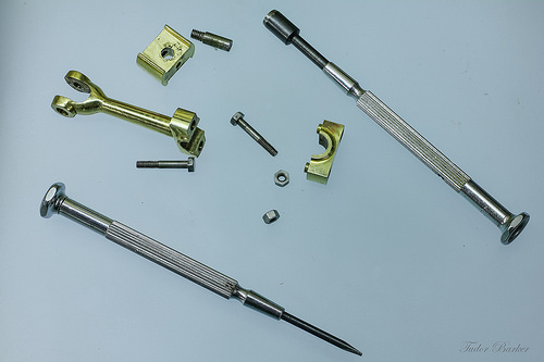
Connecting Rod Disassembly prior to a bit of a Polish
precision engineering
Image by tudedude
Stuart D10 Twin Steam Engine

Precision engineering
precision engineering
Image by Spanner Dan

Besides Precision Casting Stars

Besides Precision Casting Stars

Film trailers are regarded as to be one particular of the most critical advertising and marketing strategies for the film. The primary purpose of the film trailer is to conscious about the film which is going to be released quickly in the close to future. When we go the cinemas to watch any film ahead of the film starts we saw numerous movie trailers one particular by one particular particularly those movies whose advertising and marketing has not but been started. The primary aim for this is to generate hype and the excitement among the viewers for the upcoming movies. Generally trailers are regarded to be the short film advertisement of new films. It provides hint about the story line, steel casting stars and the location of the film.

Fireplace Firebacks have been invented in the early 16th Century. Initially, fireback manufacturing was a sideline enterprise of foundries, whose main perform was lost wax casting cannon. The cannon foundries began fires against the wall as an alternative of in the center of their workshops. They needed a contraption to shield the walls of their workshops against the intense heat generated in their furnaces. The wall was subject to extreme heating and swift cooling and as a result, the wall would at some point crumble. They relied on firebacks to aid preserve the integrity of their fireplaces or the hearths.

Sandblast is a approach wherein a stream of sand is driven by a jet of compressed air or by water against a surface. This creates a strong abrasive action that can clean and abrade any surface put below the jet of these abrasive particles. Abundant components such as powdered quartz, emery, and iron globules are normally utilised as the abrasive materials in sandblast. Sandblast is broadly utilised for cleaning precision casting iron at foundries. Sandblast is also utilized for preparing diverse surfaces for painting, enameling and in the course of galvanizing. Sandblast can also be utilised in cleaning stubborn grime that has accumulated in the stonework of most buildings. Sandblast can also be used to produce frosted designs on glass by putting a suitable stencil or pattern more than a plate of glass and applied with a little sandblast. The jet of abrasive particles of the sandblast will strike the uncovered portions of the plate glass and develop that frosted impact. A sandblast operation can sometimes be a toxic undertaking.

Now-a-days trailers are such an critical component of the film publicity that one particular can find agencies known as trailer houses. Promotion and Advertising and marketing of the film depends how the film trailer is targeted in front of the film-goers, it determines the efficiency of a movie in the box office. Besides precision casting stars, producers, directors, music composer, music, lyricist, editor, choreographer, dress designer and all. Film place is also one of the key elements behind the good results of the movie. Now days on every single news channel rather than news we saw far more film trailers rather than news especially just before the releasing date of a film.

At QS Machinery, our engineers group always function closely with you, from a idea to completed merchandise, so We can supply Quality Steel Casting, lost wax casting, precision casting and downhole cable protector and so on.

Cool Metal Components China images

Cool Metal Components China images

Check out these metal components china images:

Thames Festival Weekend Finale Fireworks
metal parts china
Image by Dominic’s pics
Component of a Set / Virtual Firework Display Slideshow documenting the firework show that marked the end of the &quotthe mayor’s&quot Thames Festival in London on the evening of Sunday September 11th 2011.

The display was presented by Pains Fireworks.

A delay in the start off of the display from the scheduled time was attributed by the crowds to incompetence by &quotBumbling Boris&quot Johnson – the London Mayor – element of the British patrician &quotlimited liability&quot ruling class. &quotI’m in charge, but if something goes incorrect, somebody else will be sacked…&quot

Like the intense audio dynamic range of Taiko or Samba drumming, it is not genuinely feasible to record the visual brilliance of fireworks with a camera. You have to expertise firework displays reside, in person. These photos have been taken at the slowest sensor speed (ISO 100), maximum aperture (to minimise diffraction &quotglare&quot effects) and with a selection of exposure instances ranging from about .five to two seconds. The intense light triggered some &quotbleaching&quot of the paths of the lights, and so the colours have been enriched if Photoshop. (In retrospect I may have utilized a slightly smaller sized aperture.)In addition, the river and land areas have been selectively lightened in Photoshop. Fortuitously, a gentle breeze brought on the smoke to drift eastwards, away from my vantage point on Waterloo Bridge, so the view of the fireworks was comparatively unobstructed by smoke.

Fireworks date from at least the 7th century in China. The colours are believed to have been traditional incandescent &quotblack physique&quot bonfire colours: red, orange, yellow and white. (It is theoretically achievable to generate pale blue just by heating, but this requires impracticably high temperatures. It is not feasible to heat one thing to &quotgreen hot&quot or &quotpurple hot&quot.) It is believed that from about 1830 in Italy metal salts have been introduced to create a wider, richer hued, spectrum of colours by chemical luminescence. This strategy can be problematic, as it can be difficult to develop stable, practical, chemical compositions. It has been recommended that some shades of green are still challenging to attain.

See also:

Fireworks [Wikipedia]
Firework Colours [The chemistry of Fireworks by Reema Gondhia, Imperial College]
History of fireworks [Pyro Universe]

Thames Festival Finale Fireworks
metal parts china
Image by Dominic’s pics
Component of a Set / Virtual Firework Display Slideshow documenting the firework show that marked the end of the &quotthe mayor’s&quot Thames Festival in London on the evening of Sunday September 11th 2011.

The show was presented by Pains Fireworks.

A delay in the commence of the display from the scheduled time was attributed by the crowds to incompetence by &quotBumbling Boris&quot Johnson – the London Mayor – part of the British patrician &quotlimited liability&quot ruling class. &quotI’m in charge, but if something goes wrong, somebody else will be sacked…&quot

Like the extreme audio dynamic range of Taiko or Samba drumming, it is not actually attainable to record the visual brilliance of fireworks with a camera. You have to knowledge firework displays reside, in individual. These photos had been taken at the slowest sensor speed (ISO 100), maximum aperture (to minimise diffraction &quotglare&quot effects) and with a selection of exposure occasions ranging from about .five to two seconds. The intense light triggered some &quotbleaching&quot of the paths of the lights, and so the colours have been enriched if Photoshop. (In retrospect I may possibly have used a slightly smaller aperture.)In addition, the river and land places have been selectively lightened in Photoshop. Fortuitously, a gentle breeze triggered the smoke to drift eastwards, away from my vantage point on Waterloo Bridge, so the view of the fireworks was comparatively unobstructed by smoke.

Fireworks date from at least the 7th century in China. The colours are believed to have been conventional incandescent &quotblack physique&quot bonfire colours: red, orange, yellow and white. (It is theoretically feasible to create pale blue just by heating, but this needs impracticably high temperatures. It is not achievable to heat one thing to &quotgreen hot&quot or &quotpurple hot&quot.) It is believed that from about 1830 in Italy metal salts were introduced to create a wider, richer hued, spectrum of colours by chemical luminescence. This method can be problematic, as it can be difficult to produce steady, sensible, chemical compositions. It has been suggested that some shades of green are still tough to accomplish.

See also:

Fireworks [Wikipedia]
Firework Colours [The chemistry of Fireworks by Reema Gondhia, Imperial College]
History of fireworks [Pyro Universe]