A handful of nice high precision engineering photos I identified:
Image from page 240 of “The Bell System technical journal” (1922)

Image by Net Archive Book Photos
Identifier: bellsystemtechni16amerrich
Title: The Bell Program technical journal
Year: 1922 (1920s)
Authors: American Telephone and Telegraph Company
Subjects: Telecommunication Electric engineering Communication Electronics Science Technologies
Publisher: [Quick Hills, N.J., and so on., American Phone and Telegraph Co.]
Contributing Library: Prelinger Library
Digitizing Sponsor: World wide web Archive
View Book Web page: Book Viewer
About This Book: Catalog Entry
View All Images: All Pictures From Book
Click here to view book on the web to see this illustration in context in a browseable online version of this book.
Text Appearing Just before Image:
an addi-tional 60-turn winding was used for checking the measurements in thelow-frequency variety. In either case the inductance was low enoughto depress any effect of distributed capacitance far below the precisionof the measurements. Measurements have been produced on a ten-ohm equal ratio arm inductance MAGNETIC LOSSES AT LOW FLUX DENSITIES 217 comparison bridge,^ and were verified at low frequencies employing a 1-ohmratio arm bridge. Calibration of the bridge and common coils wasefifected by creating measurements over the whole frequency range on acalibrated higher good quality air core coil substituted for the test coil. Themaximum correction essential on this account was about .1per cent of the resistance due to the magnetic core. The supply of alternating present was an oscillator-amplifier supply-ing approximately .four watt undistorted energy, calibrated for thesemeasurements against the Laboratories standard frequency. Thecurrent was adjusted by the insertion of resistance in series with the
Text Appearing Following Image:
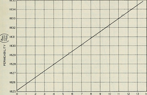
5 6 7 eight 9 H IN OERSTEADS X ten^ Fig. 2—Core permeability as measured by the ballistic galvanometer. main of the bridge input transformer, and was measured by meansof a thermocouple amongst the transformer secondary and the bridge.The bridge unbalance was amplified by signifies of an impedancecoupled amplifier for the 10-ohm bridge, and by indicates of a resistancecoupled amplifier for the 1-ohm bridge. The amplified unbalance wasobserved by means of head phones at frequencies above 200 cycles, andby means of a vibration galvanometer at lower frequencies. The d.-c.balance required bridge current of about 3 m.a. in the test coil winding,and had the identical precision as the a.-c. balance, viz., db .0002 ohm.The inductance readings had been corrected for the air space within thewinding, and had a relative accuracy of about .03 per cent, and anabsolute accuracy of around .1 per cent. 218 BELL Method TECHNICAL JOURNAL D.-C. Final results The permeability n = BmjHm of the specimen is shown as a enjoyable
Note About Images
Please note that these images are extracted from scanned web page photos that might have been digitally enhanced for readability – coloration and appearance of these illustrations may possibly not perfectly resemble the original operate.
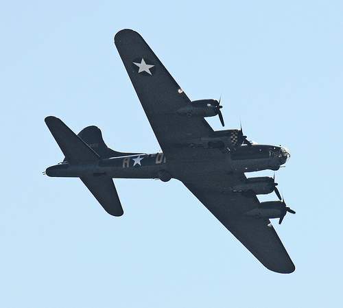
Boeing B-17 – Duxford Airshow Oct 2010

Image by Feggy Art
Boeing B-17 at Duxford Airshow October 2010.
The Boeing B-17 Flying Fortress was a four-engine heavy bomber aircraft developed in the 1930s for the United States Army Air Corps (USAAC). Competing against Douglas and Martin for a contract to develop 200 bombers, the Boeing entry outperformed each competitors and a lot more than met the Air Corps’ expectations. Though Boeing lost the contract because the prototype crashed, the Air Corps was so impressed with Boeing’s style that they ordered 13 much more B-17s for additional evaluation. From its introduction in 1938, the B-17 Flying Fortress evolved through numerous style advances.
The B-17 was primarily employed by the United States Army Air Forces (USAAF) in the daylight precision strategic bombing campaign of Planet War II against German industrial and military targets. The United States Eighth Air Force primarily based at Thorpe Abbotts airfield in England and the Fifteenth Air Force primarily based in Italy complemented the RAF Bomber Command’s evening time area bombing in Operation Pointblank to assist safe air superiority more than the cities, factories and battlefields of Western Europe in preparation for Operation Overlord. The B-17 also participated to a lesser extent in the War in the Pacific exactly where it carried out raids against Japanese shipping and airfields.
From its pre-war inception, the USAAC (later USAAF) touted the aircraft as a strategic weapon it was a potent, high-flying, extended-variety bomber that was capable to defend itself, and to return house despite comprehensive battle harm. It rapidly took on mythic proportions, and widely circulated stories and photographs of B-17s surviving battle damage increased its iconic status. With a service ceiling higher than any of its Allied contemporaries, the B-17 established itself as an effective weapons system, dropping more bombs than any other U.S. aircraft in Planet War II. Of the 1.5 million metric tons of bombs dropped on Germany by U.S. aircraft, 640,000 tons had been dropped from B-17s.
Common characteristics
•Crew: 10: Pilot, co-pilot, navigator, bombardier/nose gunner, flight engineer-best turret gunner, radio operator, waist gunners (2), ball turret gunner, tail gunner
•Length: 74 ft four in (22.66 m)
•Wingspan: 103 ft 9 in (31.62 m)
•Height: 19 ft 1 in (5.82 m)
•Wing area: 1,420 sq ft (131.92 m2)
•Airfoil: NACA 0018 / NACA 0010
•Aspect ratio: 7.57
•Empty weight: 36,135 lb (16,391 kg)
•Loaded weight: 54,000 lb (24,500 kg)
•Max takeoff weight: 65,500 lb (29,700 kg)
•Powerplant: 4× Wright R-1820-97 Cyclone turbo supercharged radial engines, 1,200 hp (895 kW) each and every
Overall performance
•Maximum speed: 287 mph (249 kn, 462 km/h)
•Cruise speed: 182 mph (158 kn, 293 km/h)
•Range: 2,000 mi (1,738 nmi, 3,219 km) with two,700 kg (six,000 lb) bombload
•Service ceiling: 35,600 ft (ten,850 m)
•Rate of climb: 900 ft/min (four.six m/s)
•Wing loading: 38. lb/sq ft (185.7 kg/m2)
•Power/mass: .089 hp/lb (150 W/kg)
Armament
•Guns: 13 × .50 in (12.7 mm) M2 Browning machine guns in 4 turrets in dorsal, ventral, nose and tail, 2 in waist positions, two beside cockpit and 1 in the reduce dorsal position
•Bombs:
•Short range missions (<400 mi): 8,000 lb (three,600 kg)
•Long variety missions (≈800 mi): four,500 lb (two,000 kg)
•Overload: 17,600 lb (7,800 kg)
Text and specifications based on Wikipedia write-up below the Inventive Commons License for non-profit use.
This is the Boeing B17G-105-VE Flying Fortress 124485 G-BEDF (Memphis Belle)