Some cool machining engineering pictures:
Image from web page 485 of “American engineer and railroad journal” (1893)

Image by World wide web Archive Book Photos
Identifier: americanengineer68newy
Title: American engineer and railroad journal
Year: 1893 (1890s)
Authors:
Subjects: Railroad engineering Engineering Railroads Railroad cars
Publisher: New York : M.N. Forney
Contributing Library: Carnegie Library of Pittsburgh
Digitizing Sponsor: Lyrasis Members and Sloan Foundation
View Book Web page: Book Viewer
About This Book: Catalog Entry
View All Photos: All Pictures From Book
Click right here to view book on-line to see this illustration in context in a browseable on the internet version of this book.
Text Appearing Before Image:
qually satisfactory. The tiny enginedrives drills and valve-facing tools straight by implies of theStow flexible shaft. The identical practise also prevails here, ason the other road, in the building of pistons. A hollowpislon with rings sprung in is employed, but the rings are muchnarrower than on the New York, Lake Erie & Western. Mr.Foster makes use of a ring only | in. wide, and finds them perfectlysatisfactory. There is a strategy of holding the split rings out 496 THE AMERICAN ENGINEER [November, 1894. right here, nonetheless, that—to us at least—is novel. It is well knownthat if a ring is turned to a bigger diameter than that of thecylinder in which it is to run, when it is sprung in it will beout of round. To obviate this difficulty and, at the same time,hold an outward pressure on the ring, it is turned to match thecylinder. Yet another and slightly heavier ring is turned to adiameter a trifle bigger than the inside of the outer ring, andthe outer ring slipped more than it. Then, wheu they are both com-
Text Appearing Soon after Image:
BALANCED VALVE, FALL BROOK COAL CO. pressed and place in thecylinder, the outer ring is round, whilethe inner keeps it nicely out against the walls. The vehicle shops adjoin the machine shop, and are fitted withthe usual complement of woodworking tools. The floor roomconsists of three tracks, each capable of holding 5 automobiles. AllCars coming in for rebuilding and all new rolling stock areequipped with the Gould coupler and the Westinghouse airbrake. The nicknames bestowed up-on a variety of varieties of locomotivesby the men constructing or runningthem have come to have a trulytechnical significance but it is sel-dom that a nickname is acceptedby the motive energy departmentwith the gravity of a name appliedto one particular of the locomotives on thisroad. All the engines have namesas nicely as numbers, although theformer are a mere ornament andnot used in reports or orders. Acertain locomotive had the misfor-tune to jump from a high trestle atIthaca, and was forthwith dubbedthe Sam Patrh by the males. Re-pairs naturally
Note About Pictures
Please note that these pictures are extracted from scanned page images that might have been digitally enhanced for readability – coloration and appearance of these illustrations may possibly not completely resemble the original work.
Image from page 423 of “Manual for railroad engineers and engineering students : containing the guidelines and tables necessary for the location, building, and equipment of railroads as constructed in the United States” (1883)

Image by Web Archive Book Pictures
Identifier: manualforrailroa00vose
Title: Manual for railroad engineers and engineering students : containing the rules and tables needed for the place, building, and equipment of railroads as constructed in the United States
Year: 1883 (1880s)
Authors: Vose, George L. (George Leonard), 1831-1910
Subjects: Railroad engineering
Publisher: Boston : Lee and Shepard
Contributing Library: Northeastern University, Snell Library
Digitizing Sponsor: Northeastern University, Snell Library
View Book Page: Book Viewer
About This Book: Catalog Entry
View All Images: All Pictures From Book
Click right here to view book on-line to see this illustration in context in a browseable on-line version of this book.
Text Appearing Before Image:
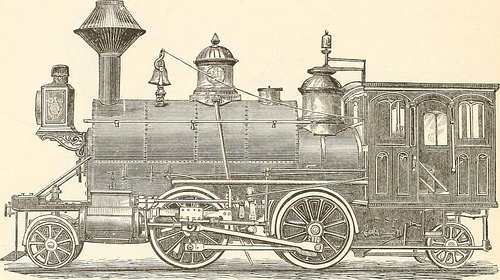
Fig- 157- Fig. 157 and the addition of a related truck behind gives thetank engine, made by Mr. Hudson, of the Rogers Locomotive 398 MANUAL FOR RAILROAD ENGINEERS. Functions, shown in Fig. 158, a most excellent machine for switching,construction, branch, and even light passenger service.*
Text Appearing Soon after Image:
Fig. 158. Iig- 1S9 shows a six-wheeled tank engine, which, upon a toler-ably straight track, is a quite effective machine, but upon sharp
Note About Images
Please note that these images are extracted from scanned web page photos that may possibly have been digitally enhanced for readability – coloration and look of these illustrations may not completely resemble the original work.