3 axis milling machine eBay auctions you should keep an eye on:
[wprebay kw=”3+axis+milling+machine” num=”0″ ebcat=”-1″]
[wprebay kw=”3+axis+milling+machine” num=”1″ ebcat=”-1″]
Rapid Prototyping China
3 axis milling machine eBay auctions you should keep an eye on:
[wprebay kw=”3+axis+milling+machine” num=”0″ ebcat=”-1″]
[wprebay kw=”3+axis+milling+machine” num=”1″ ebcat=”-1″]
A few nice precision engineered products images I found:
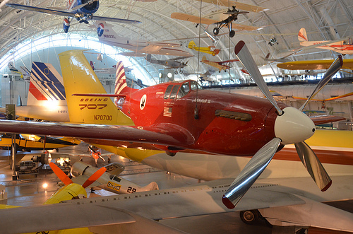
Steven F. Udvar-Hazy Center: North American P-51C, "Excalibur III", with tails of Concorde & Boeing 707 in background

Image by Chris Devers
Quoting Smithsonian National Air and Space Museum | North American P-51C, "Excalibur III":
On May 29, 1951, Capt. Charles F. Blair flew Excalibur III from Norway across the North Pole to Alaska in a record-setting 10½ hours. Using a system of carefully plotted "sun lines" he developed, Blair was able to navigate with precision where conventional magnetic compasses often failed. Four months earlier, he had flown Excalibur III from New York to London in less than 8 hours, breaking the existing mark by over an hour.
Excalibur III first belonged to famed aviator A. Paul Mantz, who added extra fuel tanks for long-distance racing to this standard P-51C fighter. With it Mantz won the 1946 and 1947 Bendix air race and set a transcontinental speed record in 1947 when the airplane was named Blaze of Noon. Blair purchased it from Mantz in 1949 and renamed it Excalibur III, after the Sikorsky VS-44 flying boat he flew for American Export Airlines.
Gift of Pan American World Airways
Manufacturer:
North American Aircraft Company
Date:
1944
Country of Origin:
United States of America
Dimensions:
Wingspan: 11.3 m (37 ft)
Length: 9.8 m (32 ft 3 in)
Height: 3.9 m (12 ft 10 in)
Weight, empty: 4,445 kg (9,800 lb)
Weight, gross: 5,052 kg (11,800 lb)
Top speed: 700 km/h (435 mph)
Materials:
Overall: Aluminum
Physical Description:
Single seat, single engine, low wing monoplane, World War II fighter modified for racing.
• • • • •
Quoting Smithsonian National Air and Space Museum | Boeing 367-80 Jet Transport:
On July 15, 1954, a graceful, swept-winged aircraft, bedecked in brown and yellow paint and powered by four revolutionary new engines first took to the sky above Seattle. Built by the Boeing Aircraft Company, the 367-80, better known as the Dash 80, would come to revolutionize commercial air transportation when its developed version entered service as the famous Boeing 707, America’s first jet airliner.
In the early 1950s, Boeing had begun to study the possibility of creating a jet-powered military transport and tanker to complement the new generation of Boeing jet bombers entering service with the U.S. Air Force. When the Air Force showed no interest, Boeing invested million of its own capital to build a prototype jet transport in a daring gamble that the airlines and the Air Force would buy it once the aircraft had flown and proven itself. As Boeing had done with the B-17, it risked the company on one roll of the dice and won.
Boeing engineers had initially based the jet transport on studies of improved designs of the Model 367, better known to the public as the C-97 piston-engined transport and aerial tanker. By the time Boeing progressed to the 80th iteration, the design bore no resemblance to the C-97 but, for security reasons, Boeing decided to let the jet project be known as the 367-80.
Work proceeded quickly after the formal start of the project on May 20, 1952. The 367-80 mated a large cabin based on the dimensions of the C-97 with the 35-degree swept-wing design based on the wings of the B-47 and B-52 but considerably stiffer and incorporating a pronounced dihedral. The wings were mounted low on the fuselage and incorporated high-speed and low-speed ailerons as well as a sophisticated flap and spoiler system. Four Pratt & Whitney JT3 turbojet engines, each producing 10,000 pounds of thrust, were mounted on struts beneath the wings.
Upon the Dash 80’s first flight on July 15, 1954, (the 34th anniversary of the founding of the Boeing Company) Boeing clearly had a winner. Flying 100 miles per hour faster than the de Havilland Comet and significantly larger, the new Boeing had a maximum range of more than 3,500 miles. As hoped, the Air Force bought 29 examples of the design as a tanker/transport after they convinced Boeing to widen the design by 12 inches. Satisfied, the Air Force designated it the KC-135A. A total of 732 KC-135s were built.
Quickly Boeing turned its attention to selling the airline industry on this new jet transport. Clearly the industry was impressed with the capabilities of the prototype 707 but never more so than at the Gold Cup hydroplane races held on Lake Washington in Seattle, in August 1955. During the festivities surrounding this event, Boeing had gathered many airline representatives to enjoy the competition and witness a fly past of the new Dash 80. To the audience’s intense delight and Boeing’s profound shock, test pilot Alvin "Tex" Johnston barrel-rolled the Dash 80 over the lake in full view of thousands of astonished spectators. Johnston vividly displayed the superior strength and performance of this new jet, readily convincing the airline industry to buy this new airliner.
In searching for a market, Boeing found a ready customer in Pan American Airway’s president Juan Trippe. Trippe had been spending much of his time searching for a suitable jet airliner to enable his pioneering company to maintain its leadership in international air travel. Working with Boeing, Trippe overcame Boeing’s resistance to widening the Dash-80 design, now known as the 707, to seat six passengers in each seat row rather than five. Trippe did so by placing an order with Boeing for 20 707s but also ordering 25 of Douglas’s competing DC-8, which had yet to fly but could accommodate six-abreast seating. At Pan Am’s insistence, the 707 was made four inches wider than the Dash 80 so that it could carry 160 passengers six-abreast. The wider fuselage developed for the 707 became the standard design for all of Boeing’s subsequent narrow-body airliners.
Although the British de Havilland D.H. 106 Comet and the Soviet Tupolev Tu-104 entered service earlier, the Boeing 707 and Douglas DC-8 were bigger, faster, had greater range, and were more profitable to fly. In October 1958 Pan American ushered the jet age into the United States when it opened international service with the Boeing 707 in October 1958. National Airlines inaugurated domestic jet service two months later using a 707-120 borrowed from Pan Am. American Airlines flew the first domestic 707 jet service with its own aircraft in January 1959. American set a new speed mark when it opened the first regularly-scheduled transcontinental jet service in 1959. Subsequent nonstop flights between New York and San Francisco took only 5 hours – 3 hours less than by the piston-engine DC-7. The one-way fare, including a surcharge for jet service, was 5.50, or 1 round trip. The flight was almost 40 percent faster and almost 25 percent cheaper than flying by piston-engine airliners. The consequent surge of traffic demand was substantial.
The 707 was originally designed for transcontinental or one-stop transatlantic range. But modified with extra fuel tanks and more efficient turbofan engines, the 707-300 Intercontinental series aircraft could fly nonstop across the Atlantic with full payload under any conditions. Boeing built 855 707s, of which 725 were bought by airlines worldwide.
Having launched the Boeing Company into the commercial jet age, the Dash 80 soldiered on as a highly successful experimental aircraft. Until its retirement in 1972, the Dash 80 tested numerous advanced systems, many of which were incorporated into later generations of jet transports. At one point, the Dash 80 carried three different engine types in its four nacelles. Serving as a test bed for the new 727, the Dash 80 was briefly equipped with a fifth engine mounted on the rear fuselage. Engineers also modified the wing in planform and contour to study the effects of different airfoil shapes. Numerous flap configurations were also fitted including a highly sophisticated system of "blown" flaps which redirected engine exhaust over the flaps to increase lift at low speeds. Fin height and horizontal stabilizer width was later increased and at one point, a special multiple wheel low pressure landing gear was fitted to test the feasibility of operating future heavy military transports from unprepared landing fields.
After a long and distinguished career, the Boeing 367-80 was finally retired and donated to the Smithsonian in 1972. At present, the aircraft is installated at the National Air and Space Museum’s new facility at Washington Dulles International Airport.
Gift of the Boeing Company
Manufacturer:
Boeing Aircraft Co.
Date:
1954
Country of Origin:
United States of America
Dimensions:
Height 19′ 2": Length 73′ 10": Wing Span 129′ 8": Weight 33,279 lbs.
Physical Description:
Prototype Boeing 707; yellow and brown.
• • • • •
Quoting Smithsonian National Air and Space Museum | Concorde, Fox Alpha, Air France:
The first supersonic airliner to enter service, the Concorde flew thousands of passengers across the Atlantic at twice the speed of sound for over 25 years. Designed and built by Aérospatiale of France and the British Aviation Corporation, the graceful Concorde was a stunning technological achievement that could not overcome serious economic problems.
In 1976 Air France and British Airways jointly inaugurated Concorde service to destinations around the globe. Carrying up to 100 passengers in great comfort, the Concorde catered to first class passengers for whom speed was critical. It could cross the Atlantic in fewer than four hours – half the time of a conventional jet airliner. However its high operating costs resulted in very high fares that limited the number of passengers who could afford to fly it. These problems and a shrinking market eventually forced the reduction of service until all Concordes were retired in 2003.
In 1989, Air France signed a letter of agreement to donate a Concorde to the National Air and Space Museum upon the aircraft’s retirement. On June 12, 2003, Air France honored that agreement, donating Concorde F-BVFA to the Museum upon the completion of its last flight. This aircraft was the first Air France Concorde to open service to Rio de Janeiro, Washington, D.C., and New York and had flown 17,824 hours.
Gift of Air France.
Manufacturer:
Societe Nationale Industrielle Aerospatiale
British Aircraft Corporation
Dimensions:
Wingspan: 25.56 m (83 ft 10 in)
Length: 61.66 m (202 ft 3 in)
Height: 11.3 m (37 ft 1 in)
Weight, empty: 79,265 kg (174,750 lb)
Weight, gross: 181,435 kg (400,000 lb)
Top speed: 2,179 km/h (1350 mph)
Engine: Four Rolls-Royce/SNECMA Olympus 593 Mk 602, 17,259 kg (38,050 lb) thrust each
Manufacturer: Société Nationale Industrielle Aérospatiale, Paris, France, and British Aircraft Corporation, London, United Kingdom
Physical Description:
Aircaft Serial Number: 205. Including four (4) engines, bearing respectively the serial number: CBE066, CBE062, CBE086 and CBE085.
Also included, aircraft plaque: "AIR FRANCE Lorsque viendra le jour d’exposer Concorde dans un musee, la Smithsonian Institution a dores et deja choisi, pour le Musee de l’Air et de l’Espace de Washington, un appariel portant le couleurs d’Air France."
Steven F. Udvar-Hazy Center: Photomontage of Overview of the south hangar, including B-29 “Enola Gay” and Concorde

Image by Chris Devers
Red Bud, Illinois (PRWEB) August 21, 2014
For the second time in four years, Southern Illinois Crankshaft (SIC) of Red Bud, Ill., is in a mode for growth and expanding the line of products they manufacture. Mike Ward, Commercial Lending Officer with National Bank, has worked with SIC owners Michael and Jeannie Schaefer since 2011 to help make financing a reality. SIC has become a precision manufacturer of crankshafts for oil and gas pumps and high-performance diesel engines.
The inception of the current expansion came as a customer request. During a recent forecast meeting with one of SIC larger customers, the purchasing manager at the company requested that SIC consider expanding their services to cover key parts used in high pressure hydraulic fracking operations. Because of SIC’s track record of meeting production times, producing a quality part, and keeping costs under control, the customer suggested expanding to meet their growing demands. National Bank took the time to understand the potential for SIC to be successful in these new areas and has enjoyed being a part of the Schaefer’s continued prosperity and job creation. Southern Illinois Crankshaft, Inc. will add 15,000 square feet to its current location. As part of the expansion, a new CNC horizontal boring and milling machine will handle product up to 22,000 pounds.
SIC was founded in 1985 by Michael and Jeannie Schaefer to manually machine crank shafts, for the agricultural, salvage, and heavy duty construction industries. The business started out in a 40’ X 40’ building in Evansville, Illinois. In 2005 SIC began manufacturing precision pump cranks and has developed strong relationships with the larger pump manufacturers. With the partnership of Mike Ward and National Bank, SIC has been able to plan out a multi stage growth plan that continues to this day. SIC is currently located in a 13,960 square foot facility with a state of the art line of CNC machining centers. “Our dedication to quality is without rival. We have delivered on our commitments 98% of the time in 2013,” said Michael Schaefer, president of SIC. Strict quality control has enabled SIC to achieve an unprecedented scrap rate of less than 1%. SIC has continued to grow by manufacturing pump crankshafts for the oil and gas industry.
National Bank is headquartered in Hillsboro, Illinois with 11 locations in South Central Illinois. The bank can be contacted from 8:30am to 4:30pm Monday through Friday and 8:30am to 12:00pm on Saturday at 800-717-3991.
Unexploded Israeli ordnance creates more danger for Gazans
Medhat al-Batash, a technical department official for the explosives engineering unit in Gaza, which is affiliated with the Ministry of Interior, said that the UXOs of the current war are more dangerous than in any previous war. … “Parts of guidance …
Read more on Al-Monitor
FARO Technologies Announces 3rd Annual 3D Documentation Conference
FARO welcomes participants from a variety of sectors such as Accident Reconstruction, Architecture, Civil China Engineering, Facilities Management, Forensics, Surveying, and others. For more information about the 2014 FARO 3D Documentation Conference, visit …
Read more on Wall Street Journal
High Precision China Engineering on eBay:
[wprebay kw=”high+precision+engineering” num=”0″ ebcat=”-1″]
[wprebay kw=”high+precision+engineering” num=”1″ ebcat=”-1″]
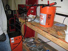
A CNC wood router is a Numerical control tool that creates objects from wood. Parts of a project can be made and then assembled using a router to produce a complete project.
The CNC router works like a printer. Work is composed on a computer and then the design or drawing is sent to the CNC router for the hard copy. This outputs a 3-dimensional copy of the work. The CNC router uses a cutting tool instead of an ink jet.
The cutting tool is generally a router but other cutters can be used as well.
The CNC works on the Cartesian coordinate system (X, Y, Z) for 3D motion control. CNC stands for computer numerically controlled cutting tool. This gives the computer a printer like ability to drive a CNC machine to make parts.
For engraving and general purpose cutting all that is needed is some material to engrave or cut on and an engraving or cutting tool bit.
A file of a picture or part has to be converted to g-code. Clamp the work piece down and then use the driver program to zero the CNC and run the g-code file. This will command the CNC to make the desired parts for you, quickly and accurately. Use it for all kinds of projects to make PCBs, gears, molds, etc.
The CNC Router is great for hobbies, engineering prototyping, product development, art, robotic education, and production work.
How it works
A CNC wood router uses CNC (computer numerical control) and is similar to a metal CNC mill with the following differences:
àThe wood router typically spins faster — with a range of 13,000 to 24,000 RPM
àLow end hobby grade machines typically uses smaller tools — typical shank size 20 mm or at most 25 mm. Professional quality machines frequently use surface facing tools up to 3″ in diameter or more, and spindle power exceeding 15 horsepower. China Machines capable of routing heavy material at many hundreds of inches per minute are common.
àSome machines use smaller toolholders MK2 (Morse taper #2 – on older machines), ISO-30, HSK-63 or the tools just get held in a collet tool holder affixed directly to the spindle nose. ISO-30 and HSK-63 are rapid-change toolholding systems. HSK-63 has begun to supplant the ISO-30 as the rapid change standard in recent years.
A wood router is controlled in the same way as a metal mill, but there is a lot of CAM and CAD software like Artcam, Mastercam, Bobcad, and Featurecam specifically for wood routers.
Wood with different grain must be approached with unique strategies, and wood CAM software is less likely to need to have hog-out strategies than the metal ones. Wood routers are frequently used to machine other soft materials such as plastics at high speed.
Typical three-axis CNC wood routers are generally much bigger than their metal shop counterparts. 5′ x 5′, 4′ x 8′, and 5′ x 10′ are typical bed sizes for wood routers. But can be built to accommodate very large sizes up to, but not limited to 12′ x 100′. Most table routers use a three motor drive system (xyz) utilizing either servo or stepper motors that drive the router motor via a gantry system. The gantry system isolates the XYZ movement in the top part of the machine with a stationary table holding the workpiece. Many CNC metal mills have the cutter motor moving on the Z axis, and a table which moves in X and Y for added stability.
Many wood routers can run at machining speeds of 25 metres/min (linear) or faster with a few machines such as the Anderson capable of 40 metres/min, Onsrud capable of 86 metres/min.
For more information on CNC Wood Router you can visit http://www.homag-india.com/
This is Jon from Indian SEO, you can check Homag India Website for Woodworking machines.
precision milling eBay auctions you should keep an eye on:
[wprebay kw=”precision+milling” num=”0″ ebcat=”-1″]
[wprebay kw=”precision+milling” num=”1″ ebcat=”-1″]
Some cool milling and machining images:
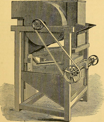
Image from page 56 of “Descriptive pamphlet of the Richmond Mill Furnishing Works: all sizes of mill stones and complete grinding and bolting combined husk or portable flouring mills, portable corn and feed mills; smut and separating machines; zigzag and

Image by Internet Archive Book Images
Identifier: descriptivepamph00rich
Title: Descriptive pamphlet of the Richmond Mill Furnishing Works: all sizes of mill stones and complete grinding and bolting combined husk or portable flouring mills, portable corn and feed mills; smut and separating machines; zigzag and oat separators, dustless separators, warehouse separators, water wheels; mill shafting; pulleys; spur and bevel, iron and core, gearing ..
Year: 1873 (1870s)
Authors: Richmond Mill Furnishing Works. [from old catalog]
Subjects: Nordyke, Marmon & Company Flour industry Milling machinery Mills and mill-work
Publisher: Richmond, Ind., Telegram Steam Print. Co.
View Book Page: Book Viewer
About This Book: Catalog Entry
View All Images: All Images From Book
Click here to view book online to see this illustration in context in a browseable online version of this book.
Text Appearing Before Image:
ank, will be required. TABLE OF DIMENSIOKS. No S o Height fromwhere wheat en-ters to floor. SIZE ON FLOOR. 1^ DIAMETER OFPULLEY. Height from Floor to Centre of Pulley. CAPACITY PER HOUR. 0 5 ft 5 in. 4 ft 2 ft 2 in. 700 6 in-4inface 1 foot. 10 to 15 bu 1 6 ft 2 In. 5 ft 6 in. 2 ft 2 in. 700 7 in-1 in face 1 foot. 20 to 30 bu 2 6 ft 10 in 6 ft 2 in. 2 ft 8 in. 625 10 in-5 in face 1 foot 2 in. 40 to 60 bu 3 7 ft 6 in. .5 ItOin. 3 ft 1 in. 550 14 in-6 in face 1 foot 4 in. 100 to 125 bu £ 2 3 7 ft 8 in. 5 ft 2 in. 2 ft 8 in. 650 10 in-5 in face 1 footlin. 40 to 60 bu & 3 7 ft 11 in 5 ft 3 in. 3ft2in. 550 14 in-6 in face 1 footl in. 100 to 125 bu 8 ft 2 in. 5 ft 6 in. 3 ft 6 in. 500 14tol6in-8inface 1 footl in. 125 to 150 bu ^ 5 3 I 8 ft 2 in. 5 ft 4 in. 3 ft 9 in. 450 18to24in-8inface 1 foot 4 in. 175 to 2001 bu RICHMOND MILL FURNISHING WORKS. 45 DUSTLESS OAT SEPARATOR AND ZIGZAG. With two or four Wheat Riddles and Cockle Riddle. j^ATENTED ^PRIL 9, 1861; JIe-ISSUED, A.PRIL 1 9, 187I.
Text Appearing After Image:
This China Machine is named Dustless Separator, because theDust is separated from the wheat, conveyed out of the mill, anddeposited in a dust room, before the grain passes to the riddles; thewheat and screenings are left free from dust. 7 46 RICHMOND MILL FURNISHING WORKS. Its operation is as follows:—The grain enters the China Machine at thehopper, which is shown, where it receives the first blast; then passesthrough two to four wheat riddles in succession, and over a cockleriddle into the second blast. The riddles deposit oats, sticks, weeds,ergot, rat-balls, etc., in suitable spouts; the heavy screenings fall intoa hopper and are spouted off. This China Machine has none but suctionblasts, and is offered to the milling community as a first-class Separa-tor. Dimensions and Capacity. No. Capacityper hour. Size onfloor. Extreme -n nHeight. P«y- Kev. perminute. 23 30 to 40 bush.60 to 80 bush. 30 to 40 bush.60 to 80 bush. 33x3445x34 33x3445x34, 5 ft. 4 in 5 ft. 5 in 6 ft. 2 in6 ft. 3 in 6 in.6 in. 4404
Note About Images
Please note that these images are extracted from scanned page images that may have been digitally enhanced for readability – coloration and appearance of these illustrations may not perfectly resemble the original work.
Image from page 27 of “Descriptive pamphlet of the Richmond Mill Furnishing Works: all sizes of mill stones and complete grinding and bolting combined husk or portable flouring mills, portable corn and feed mills; smut and separating machines; zigzag and
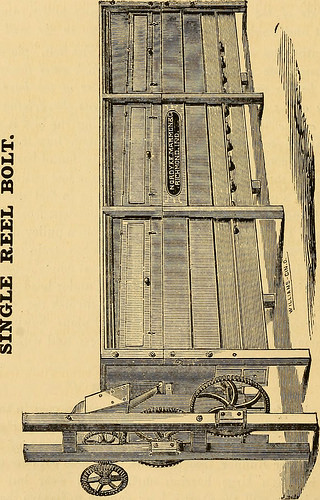
Image by Internet Archive Book Images
Identifier: descriptivepamph00rich
Title: Descriptive pamphlet of the Richmond Mill Furnishing Works: all sizes of mill stones and complete grinding and bolting combined husk or portable flouring mills, portable corn and feed mills; smut and separating machines; zigzag and oat separators, dustless separators, warehouse separators, water wheels; mill shafting; pulleys; spur and bevel, iron and core, gearing ..
Year: 1873 (1870s)
Authors: Richmond Mill Furnishing Works. [from old catalog]
Subjects: Nordyke, Marmon & Company Flour industry Milling machinery Mills and mill-work
Publisher: Richmond, Ind., Telegram Steam Print. Co.
View Book Page: Book Viewer
About This Book: Catalog Entry
View All Images: All Images From Book
Click here to view book online to see this illustration in context in a browseable online version of this book.
Text Appearing Before Image:
convenience. Wehave it shown in a small way in the cut, Fig. 3, under head of Com-plete China Grinding and Bolting Mills. Where we furnish the mills, wealways, when requested to do so, send draft and plans showing how toset up and arrange all, so that it will be a success, and without addi-tional charge. GEARED MILLS Are furnished with wood and iron gearing—wooden cogs in the driv-ing wheel. This does away with the noise and deafening clatter ofthe ordinary, or all iron geared mills. (See under head of Gear-ing, and Under Runner Geared Mills.) These cogs are of wideface, thus having a large bearing surface, and wear but slowly.Where there is one mill the shaft is long enough to receive the pulleyand one journal box outside. We often put three run of burrs,two wheat and one corn, upon one continuous shaft. This makes avery compact arrangement. In this case the mills are detached byslipping the pinion or wheel out of gear, on a sleeve provided for thepurpose. 20 DESCRIPTIVE PAMPHLET OF THE
Text Appearing After Image:
o > § a > c RICHMOND MILL FURNISHING WORKS. 21 SINGLE REEL BOLT—Complete, and Dimen-sions. (See preceding page.) Our bolts are so well known that a full description seems superflu-ous. Their constant use for fourteen years has suggested some markedchanges, which together with aWief outline of the bolt itself, we willdescribe. The object gained is a more efficient bolt for custom work,either for a Portable Mill or any flouring mill however large or small,where a bolt is wanted specially adapted to the demands of customgrinding; at the same time a bolt that can be shipped to any point ona navigable river or railroad in the United States or Territories. Wehave already sent a number of them into Northern Minnesota andWisconsin. Also, Texas, Kansas, Georgia. &c., &c. When so or-dered they are taken apart and boxed, previously marked how eachpart belongs, and drafts and description of how to set it up, sent sothat one at all skilled can put it up in the mill and have it rea
Note About Images
Please note that these images are extracted from scanned page images that may have been digitally enhanced for readability – coloration and appearance of these illustrations may not perfectly resemble the original work.

[youtube http://www.youtube.com/watch?v=N7NofmHWWPQ&fs=1&rel=0]
Introducing the latest in 3D Laser Processing capabilities from MITSUBISHI LASER the VZ20 series “Offset Head Type” 5-axis lasers provide more cutting power …
Video Rating: 4 / 5
[youtube http://www.youtube.com/watch?v=dABLbjjNTLk&fs=1&rel=0]

www.anseat.de High power laser cutting machine VARIO LASER Quick Tool Exchange of various Tool heads for Multi Purpose application of the laser machine.
McMullen Precision China Engineering Offers New CNC Services To Northern Irish …
McMullen Precision China Engineering has advanced its capabilities in CNC machining to including turning and precision milling using both chucking and bar fed lathes. Precision China engineering is responsible for all of the small but essential parts that make …
Read more on Machine Tools Online (press release)
Fiber Laser China Cutting System uses optimized China cutting head, CNC.
Mazak Optonics is part of Yamazaki Mazak Corporation (Oguchi, Japan), the global leader for the manufacture of machine tools and systems for the precision machining of metal parts, including CNC turning centers, horizontal and vertical machining …
Read more on ThomasNet News (press release) (blog)
SME success stories: Small parts, complex configurations
… 42 turning center for small part turning. Including the shop's most recent purchases, D-M “currently has 10 CNC milling centers, five China CNC lathes and an China EDM sink and wire cutter … Haas and Hardinge brands make up around 70 percent of the machine …
Read more on Canadian Metalworking